Flow sensor and manufacturing method therefor

a flow sensor and manufacturing method technology, applied in the direction of resistive material coating, liquid/fluent solid measurement, instruments, etc., can solve the problems of difficult to achieve quality stability, easy to detecting flow rate parts, and reduced pressure resistance of glass chips, etc., to achieve easy configuration, easy to form, and reduce the individual difference between flow sensors

Active Publication Date: 2009-03-26
YAMATAKE HONEYWELL CO LTD
View PDF9 Cites 16 Cited by
  • Summary
  • Abstract
  • Description
  • Claims
  • Application Information

AI Technical Summary

Benefits of technology

[0017]An object of the present invention is to provide a flow sensor that can be manufactured at a low cost and has high detection accuracy, and a manufacturing method for the flow sensor.
[0018]A specific first object of the present invention is to provide a flow sensor in which the fabrication accuracy of the cross-sectional area of a sensor flow path is improved to decrease the individual difference, by which the flow rate detection accuracy is stabilized.
[0019]Also, a specific second object of the present invention is to provide a flow sensor in which the production efficiency of flow sensor formed by bonding a flow path forming member onto the surface on which the flow rate detecting part of a sensor chip is formed can be increased, and the flow rate detecting part can be protected effectively at the manufacturing time, and a manufacturing method for the flow sensor.

Problems solved by technology

Therefore, adjustment of large span is needed, and it is difficult to achieve the stability of quality because the individual difference between the flow sensors arises.
Also, the pressure resistance of glass chip may decrease due to a minute flaw induced at the time of sandblasting.
Therefore, the flow rate detecting part is easy to break, and if dirt adheres to the flow rate detecting part, a change in heat balance between the upstream side and the downstream side of heater cannot be detected well.
As a result, the production efficiency of flow sensor decreases, and also the yield of product decreases.
However, the laser dicing device is very high in cost, and accordingly the manufacturing cost of flow sensor increases.

Method used


Image

  • Flow sensor and manufacturing method therefor
  • Flow sensor and manufacturing method therefor
  • Flow sensor and manufacturing method therefor

Examples


first embodiment

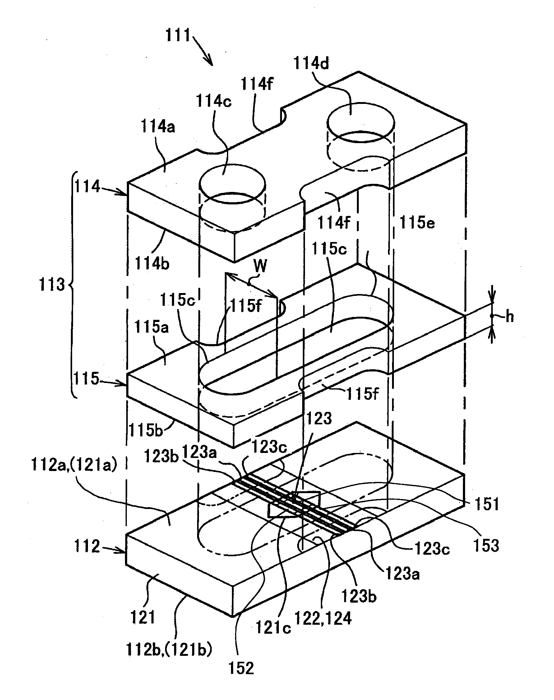
[0065]Hereunder, a flow sensor in accordance with the present invention is explained with reference to the accompanying drawings. FIG. 4 is a perspective view showing a state in which a flow sensor in accordance with the present invention is disassembled. A flow sensor 111 is formed by a sensor chip 112, and a first flow path forming member (glass chip) 114 and a second flow path forming member 115, both of which form a flow path forming member 113.

[0066]The sensor chip 112 is configured so that an electric insulating film (thin film) 122 of silicon nitride or silicon dioxide is formed on an upper surface 121a of a silicon substrate 121 having a rectangular parallelepiped shape, a flow rate detecting part (sensor part) 123 is formed at the position of the electric insulating film 122, and further the flow rate detecting part 123 is covered by an electric insulating film 124 of silicon nitride or silicon dioxide. In FIG. 4, the electric insulating films 122 and 124 are drawn so as to...

second embodiment

[0094]Successively, a flow sensor in accordance with the present invention and a manufacturing method for the flow sensor are explained with reference to the drawings. FIG. 7 is a perspective view showing the assembling of a work to which the manufacturing method for a flow sensor in accordance with the present invention is applied, and FIG. 8 is a perspective view showing the state in which one flow sensor formed by cutting the work shown in FIG. 7 into a plurality of pieces is disassembled. As indicated by the solid lines in FIG. 7, a work 211 consists of a disc-shaped first wafer 212 formed so as to provide a plurality of flow path forming members 218 after being cut individually, and a second wafer 213 that has the same disc shape as that of the first wafer 212 and is formed so as provide a plurality of sensor chips 220 after being cut individually, and is formed by bonding the first and second wafers 212 and 213 with each other.

[0095]The first wafer 212 consists of a first flow...


PUM

PropertyMeasurementUnit
heightaaaaaaaaaa
thicknessaaaaaaaaaa
sizeaaaaaaaaaa

Abstract

A flow sensor may be formed by bonding a sensor chip formed with a flow rate detecting part and a flow path-forming member that is provided on the sensor chip and is formed with a flow path for a fluid flowing in the flow rate detecting part to each other on the upper surface of a substrate. The flow path-forming member may be formed by bonding a transparent first flow path forming member and a second flow path-forming member to each other. The first flow path forming member has a plate shape, and is provided with an inflow port and a outflow port for the fluid to be measured, and the second flow path forming member has a plate shape, and is provided with a through hole that forms the flow path along the flow of the fluid flowing along the flow rate detecting part.

Description

BACKGROUND OF THE INVENTION[0001]1. Field of the Invention[0002]The present invention relates to a flow sensor suitable for the measurement of the very low flow rate of a gas etc. used in, for example, a semiconductor manufacturing apparatus.[0003]2. Description of the Related Art[0004]For example, as a flow sensor (flow rate measuring device) for detecting the flow rate of a fluid to be measured such as a gas used in a semiconductor manufacturing apparatus, a thermal flow sensor has been known which measures a very low flow rate by measuring the temperature difference of a fluid at a predetermined position by adding heat to the fluid (for example, refer to Patent Document 1: Japanese Unexamined Patent Application Publication No. 2002-168669 (pp. 5-6, FIG. 1), Patent Document 2: Japanese Unexamined Patent Application Publication No. 2004-325335 (pp. 6-7, FIG. 8), and Patent Document 3: Japanese Unexamined Patent Application Publication No. 2007-071687 (pp. 2-3, FIG. 7)). As describe...

Claims


Application Information

Patent Timeline
Patent Type & Authority Applications(United States)
IPC IPC(8): G01F1/68H01C17/06
CPCY10T29/49099G01F1/6845G01F1/692
Inventor IKE, SHINICHIHATAKEYAMA, HIROSHITSUCHIYA, SATOSHI
Owner YAMATAKE HONEYWELL CO LTD
Why Eureka
Try Eureka