Mounting system for solar panels

a solar panel and mounting system technology, applied in the field of solar panels, can solve problems such as installation errors, and achieve the effects of simplifying the final connection of external wiring, removing or changing defective modules, and simplifying the electrical assembly of modules

Inactive Publication Date: 2009-03-26
ANDALAY SOLAR
View PDF98 Cites 188 Cited by
  • Summary
  • Abstract
  • Description
  • Claims
  • Application Information

AI Technical Summary

Benefits of technology

[0008]An integrated module frame and racking system for a solar panel is disclosed. The solar panel comprises a plurality of solar modules and a plurality of splices for coupling the plurality of solar modules together. The plurality of splices provide a way to make the connected modules mechanically rigid both during transport to the roof and after mounting for the lifetime of the system, provide wiring connections between modules, provide an electrical grounding path for the modules, provide a way to add modules to the panel, and provide a way to remove or change a defective module. Connector mount assemblies are provided on the sides of the modules to simplify the electrical assembly of modules when the modules are connected together with splices and to simplify the final connection of external wiring to the module.
[0009]A solar panel in accordance with the present invention is optimized for fast and reliable installation. In addition, the fewer parts and simpler assembly technique reduces the potential for installation error. In addition, multiple modules for the panel can be supported during transport. In addition, modules and panels can be assembled closer together, improving space usage and improving aesthetics. Furthermore, individual modules can be added to and connected with existing solar panels. In addition, the use of an integrated mounting rail allows the panel to be mounted closer to the roof, improving aesthetics. Further, a minimal number of parts are utilized for the entire assembly. In addition, external wiring connections are faster and the connection of modules is faster. Furthermore there are fewer rooftop assemblies, better reliability and fewer roof penetrations. Finally, solar modules can be securely stacked and shipped with pre-installed mounting brackets, reducing shipping, packing and unpacking costs.

Problems solved by technology

In addition, the fewer parts and simpler assembly technique reduces the potential for installation error.

Method used


Image

  • Mounting system for solar panels
  • Mounting system for solar panels
  • Mounting system for solar panels

Examples


first embodiment

[0055]FIG. 2B is a conventional combiner junction box 121′. As is seen, the conventional junction box 121′ would have to be adapted to the solar module based upon the wiring 165. This would add considerable time and cost when installing the box 121′.

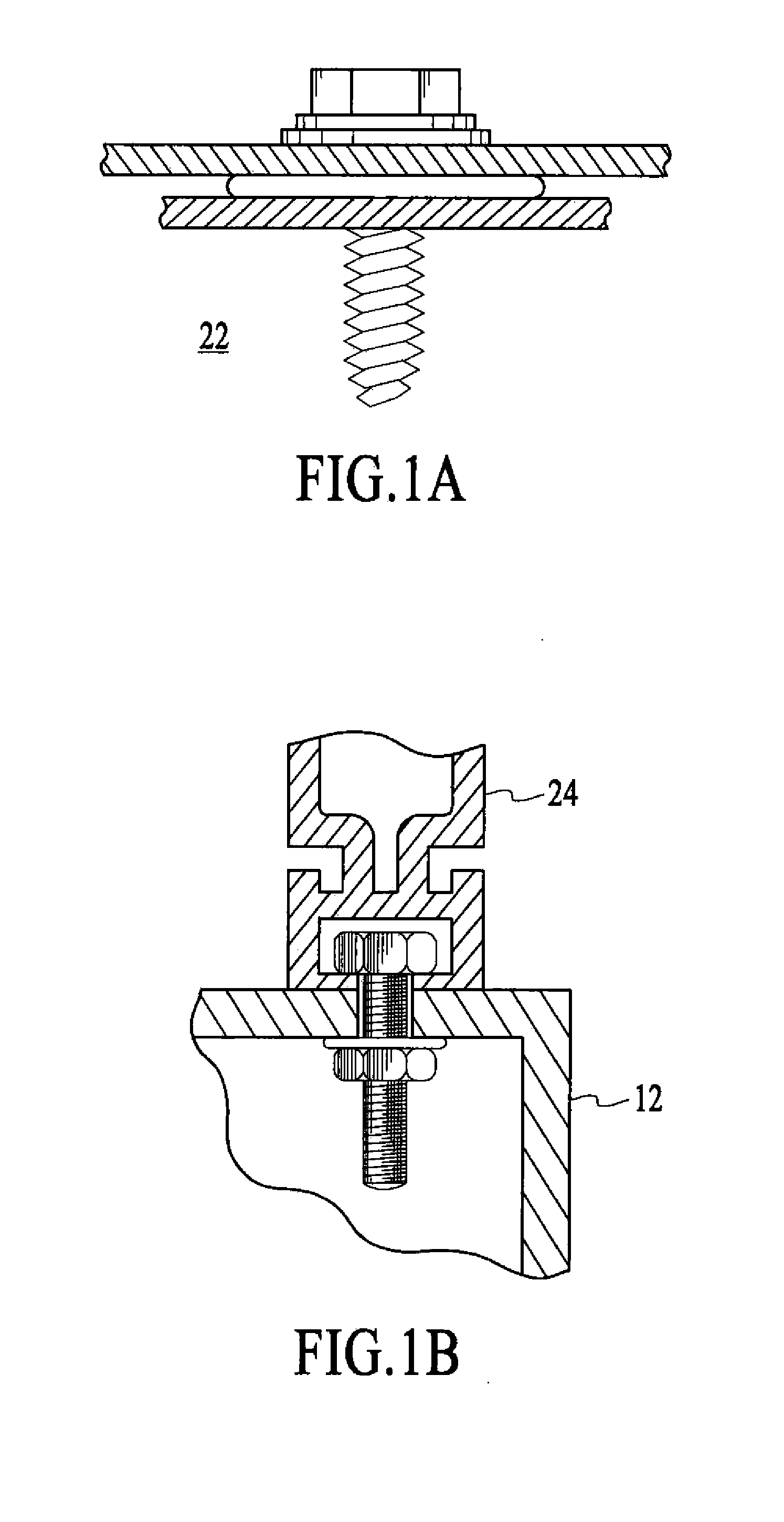
[0056]A custom combiner junction box 121″ is shown in FIG. 2C. The custom combiner junction box 121″ has several advantages over the conventional combiner junction box 121. Referring back to FIG. 2A, firstly, as is seen the connections for wiring segments 108 can be coupled directly into the connections 175 of the junction box 103′. FIG. 2D illustrates the combiner junction box 121″ coupled between two solar panels. Furthermore the custom combiner junction box 121″ is directly coupled to the outside of the solar panel and permanently fastens to the side of the panel with a bolt. The bolt also provides a grounding path to a system ground conductor.

[0057]Accordingly, the solar panel 100 requires significantly fewer parts to assemble and is...

second embodiment

[0063]FIG. 3B illustrates a threaded splice 300 that includes double screw lock 302. In this embodiment, a screw lock 302 drives the solar modules together. The screw lock 302 provides structural rigidity and also provides electrical grounding between modules. In this embodiment, the left and right hand thread 308a, 308b allow for a variety of distances between modules. The spacing between modules is dictated by the center left and right hand thread 308a and 308b. The splice 300 is coupled to the solar module using a custom wrench. The use of such wrench will be described in detail hereinafter.

[0064]FIG. 3C illustrates an embodiment of a slide cam lock for a splice. The slide cam lock 350 ensures alignment of modules through extrusion using the locking mechanism 352a and 352b. The blocks move into position to secure the splice.

third embodiment

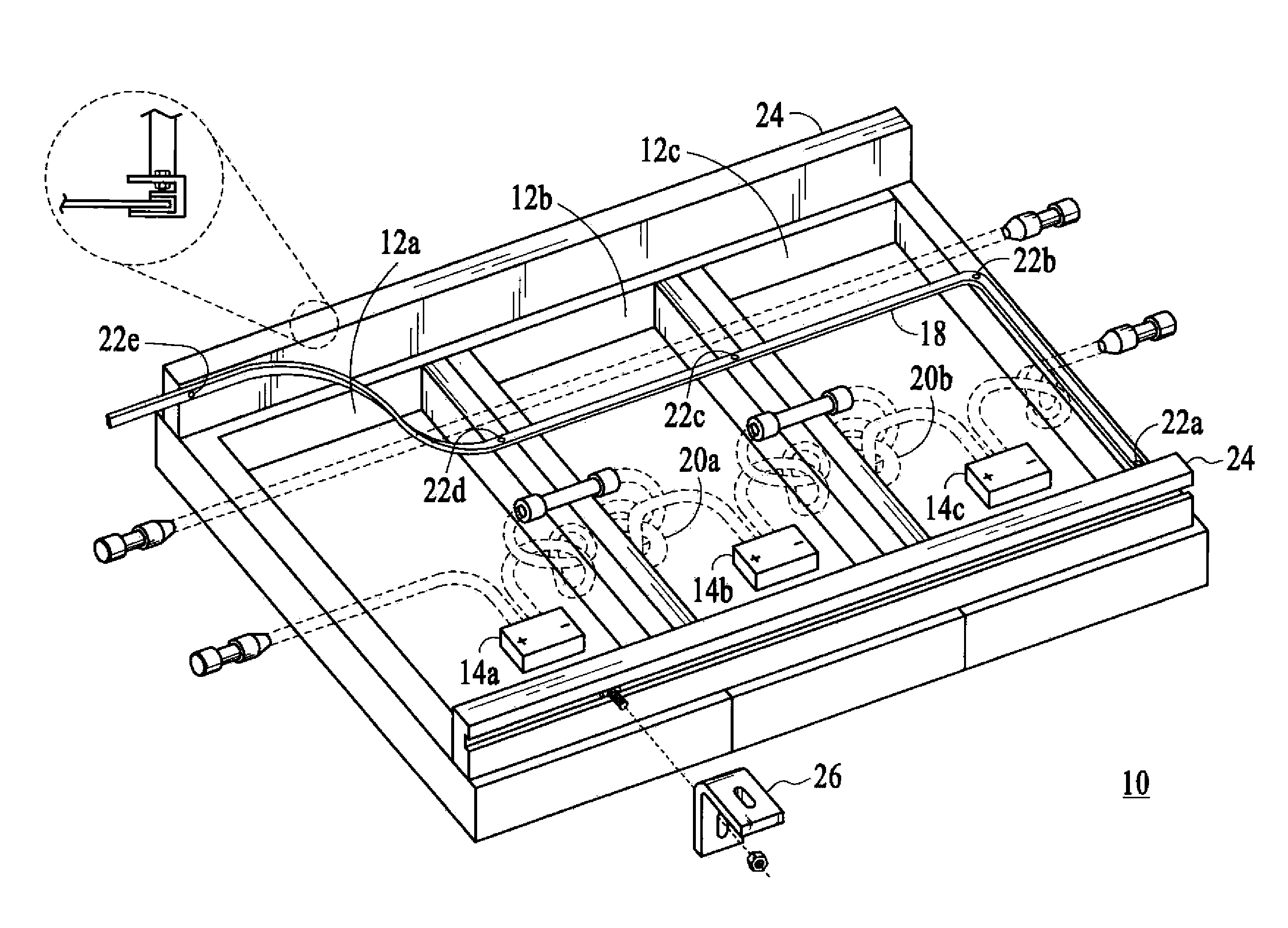
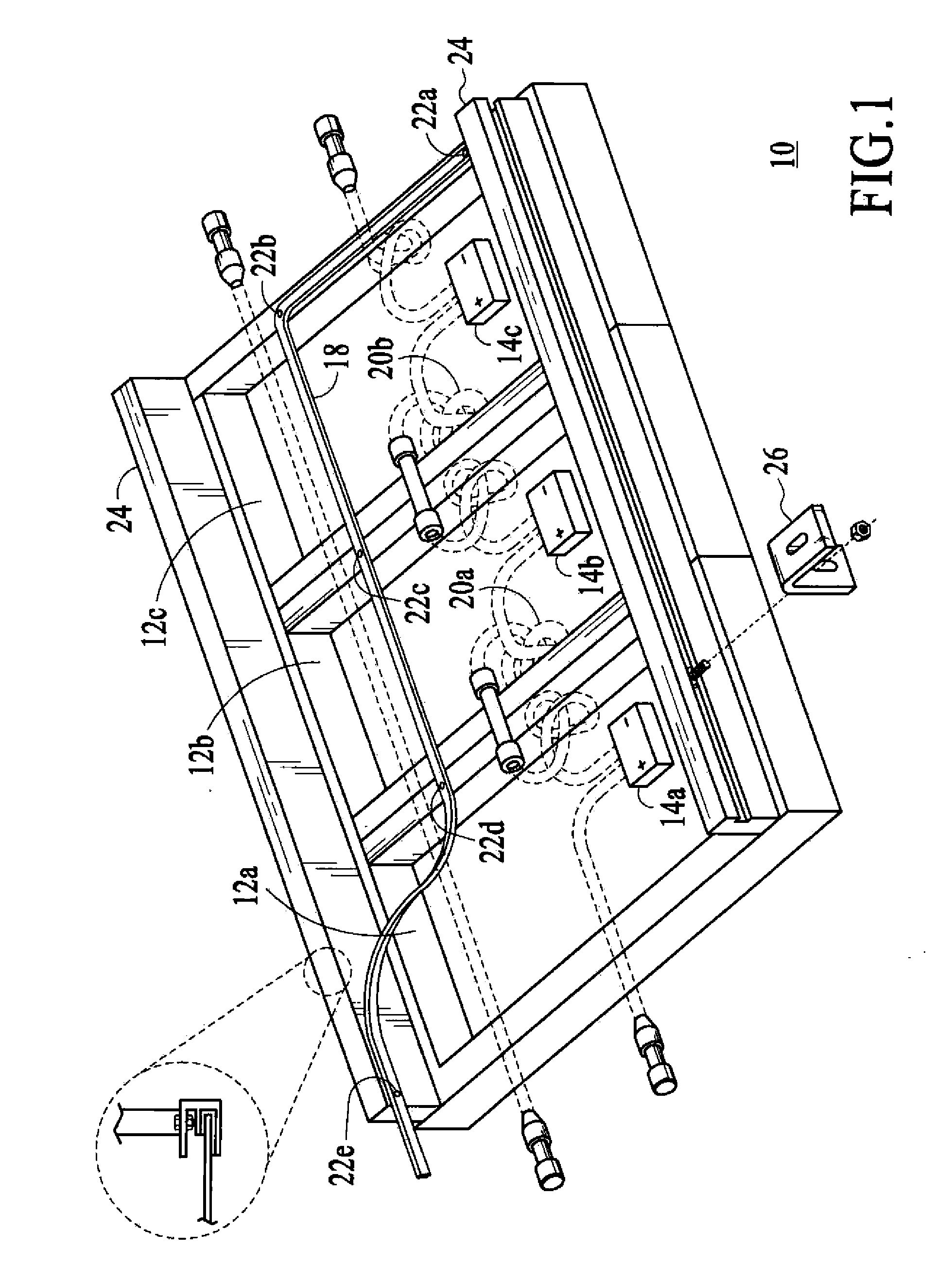
[0065]FIG. 3D illustrates a splice 104. The splice 104 is tapered to allow for easy initial assembly line up and a final tight fit between the modules 102A and 102B. In a preferred embodiment it is precisely located in the panel 100 in a centerline fashion. In a preferred embodiment the splice 104 is a tapered conductive metal to provide a grounding path between modules, and includes a sharp edge to improve grounding to each module. The splice 104 is also grooved for easy screw insertion from the top or the side of the module 102. The splice 104 precisely aligns the modules 102 and allows the assembler to compress the connector sockets 108, thereby completing an electrical connection between the two adjacent modules. The electrical connection between the two adjacent modules by the splice 304 eliminates the need to run a grounding wire between each module. As is seen only one other grounding wire is required for an entire panel assembly as long as all solar modules are connected wit...


PUM

PropertyMeasurementUnit
rigidityaaaaaaaaaa
lengthaaaaaaaaaa
shapeaaaaaaaaaa

Abstract

An integrated module frame and racking system for a solar panel is disclosed. The solar panel comprises a plurality of solar modules and a plurality of splices for coupling the plurality of solar modules together. The plurality of splices provide a way to make the connected modules mechanically rigid both during transport to the roof and after mounting for the lifetime of the system, provide wiring connections between modules, provide an electrical grounding path for the modules, provide a way to add modules to the panel, and provide a way to remove or change a defective module. Connector mount assemblies are provided on the sides of the modules to simplify the electrical assembly of modules when the modules are connected together with splices and to simplify the final connection of external wiring to the module.

Description

FIELD OF THE INVENTION[0001]The present invention relates generally to solar panels and more particularly to an assembly and mounting system for a solar panel.BACKGROUND OF THE INVENTION[0002]Solar electric systems are the most environmentally friendly way of generating electricity. To provide such solar electric systems, typically there is a solar panel, which comprises a plurality of solar modules, which are coupled together. The solar panels are typically assembled directly on the roof of a building, assembled on the ground and then mounted on a roof of a building, or installed on a dedicated ground or pole mounted frame. FIG. 1 illustrates a conventional solar panel assembly 10. The solar panel in this embodiment comprises three solar modules, 12A-12C. However, one of ordinary skill in the art recognizes there could be any number of modules and they could be in any configuration to form a solar panel.[0003]Each of the solar panel modules 12A-12C includes a junction box 14A-14C w...

Claims


Application Information

Patent Timeline
Patent Type & Authority Applications(United States)
IPC IPC(8): H01L31/05B25F1/00
CPCF24J2/045F24J2/5211F24J2/5245F24J2002/4665F24J2002/5281Y10T29/53257Y02B10/20Y02E10/47H02S30/10H02S20/23H02S40/34Y02B10/12F24S20/67F24S25/20F24S25/61F24S2025/014F24S2025/6004Y02B10/10Y02E10/50F24S25/00H01L31/05H02S40/345
Inventor CINNAMON, BARRYLEVY, EMANUEL E.BAKER, DAVID E.AU, ALEXANDER W.
Owner ANDALAY SOLAR
Why Eureka
Try Eureka