Electrostatic atomizer and hot air blower having the same

a technology of electric atomizer and hot air blower, which is applied in the direction of electrostatic spraying apparatus, hair drying, hair cleaning, etc., can solve the problems of complicated circuit structure and increase of parts coun

Inactive Publication Date: 2009-03-26
MATSUSHITA ELECTRIC WORKS LTD
View PDF9 Cites 16 Cited by
  • Summary
  • Abstract
  • Description
  • Claims
  • Application Information

AI Technical Summary

Problems solved by technology

Therefore, the pulse supply unit needs to be provided, which advantageously leads to an increase of parts count and a complicated circuit structure.

Method used


Image

  • Electrostatic atomizer and hot air blower having the same
  • Electrostatic atomizer and hot air blower having the same
  • Electrostatic atomizer and hot air blower having the same

Examples


first embodiment

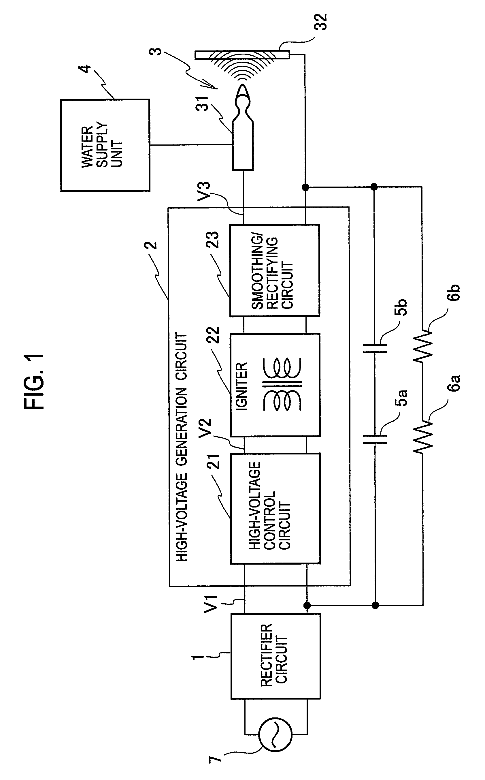
[0020]FIG. 1 shows a configuration of an electrostatic atomizer according to a first embodiment of the present invention.

[0021]With reference to FIG. 1, the electrostatic atomizer has a rectifier circuit 1, a high-voltage generation circuit 2, a discharge unit 3, a water supply unit 4, a capacitor 5 (5a, 5b), and a resistor 6 (6a, 6b).

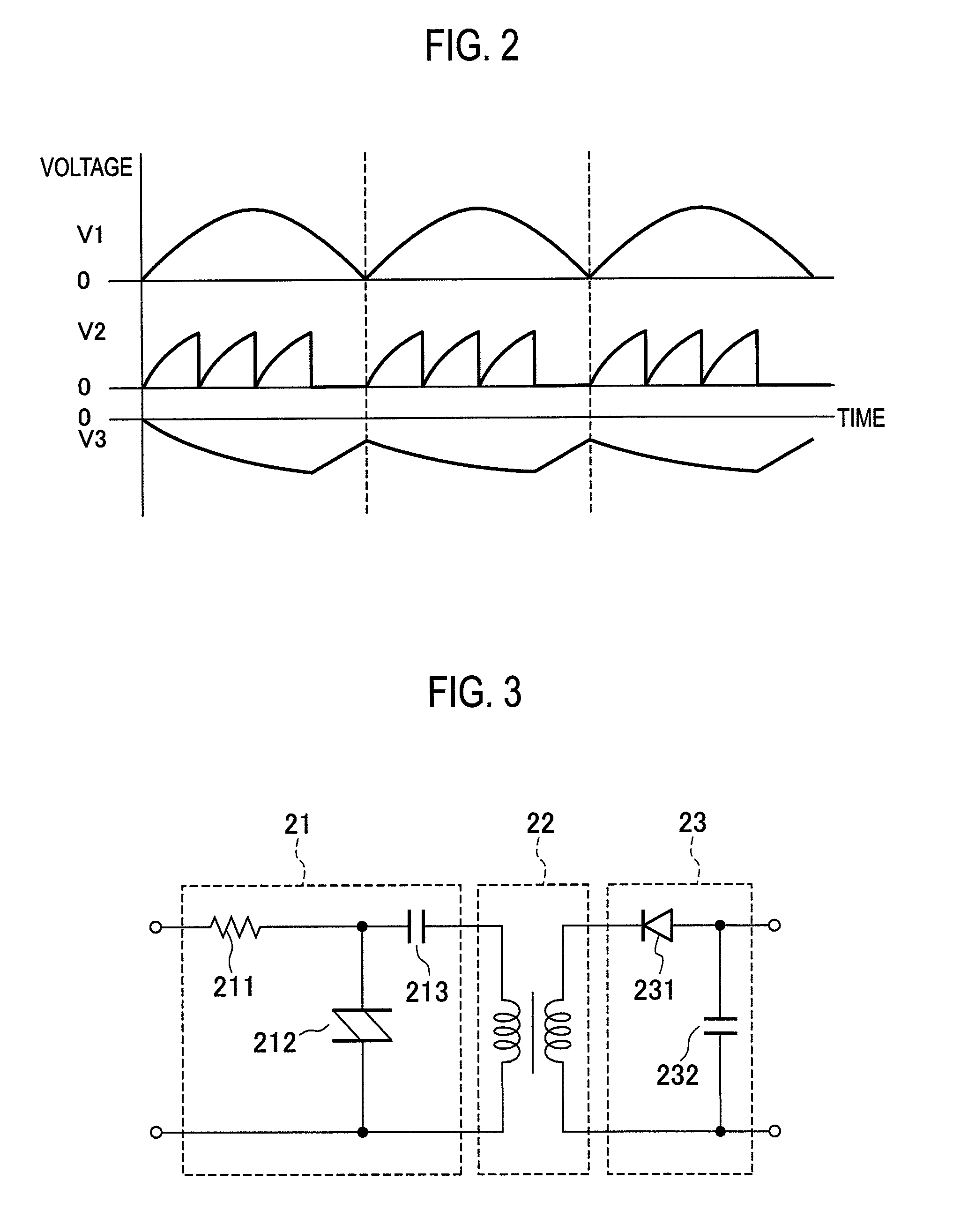
[0022]The rectifier circuit 1 rectifies an alternating current supplied from a commercial AC power supply 7 by full-wave rectification or half-wave rectification, and in the case of the full-wave rectification, the rectifier circuit 1 supplies the high-voltage generation circuit 2, a rectified signal such as that shown by V1 in a voltage waveform chart of FIG. 2.

[0023]The high-voltage generation circuit 2 includes a high-voltage control circuit 21, an igniter 22 operable as a step-up transformer, and a smoothing / rectifying circuit 23, and steps up the rectified voltage V1 supplied from the rectifier circuit 1 to generate a high-voltage pulse signal.

[00...

second embodiment

[0044]FIG. 7 shows a configuration of an electrostatic atomizer according to a second embodiment of the present invention.

[0045]With reference to FIG. 7, the second embodiment is characterized such that a current limiting circuit 8, for example, a resistor, is provided between the smoothing / rectifying circuit 23 of the high-voltage generation circuit 2 and the discharge electrode 31 of the discharge unit 3 in order to limit a current of a high-voltage pulse signal that is obtained from the high-voltage generation circuit 2 and applied via this current limiting circuit 8 to the discharge electrode 31.

[0046]By using this current limiting circuit 8 to limit the current of the pulse signal applied therethrough to the discharge electrode 31, stable generation of ion mist is ensured, in addition to the advantages achieved in the first embodiment.

third embodiment

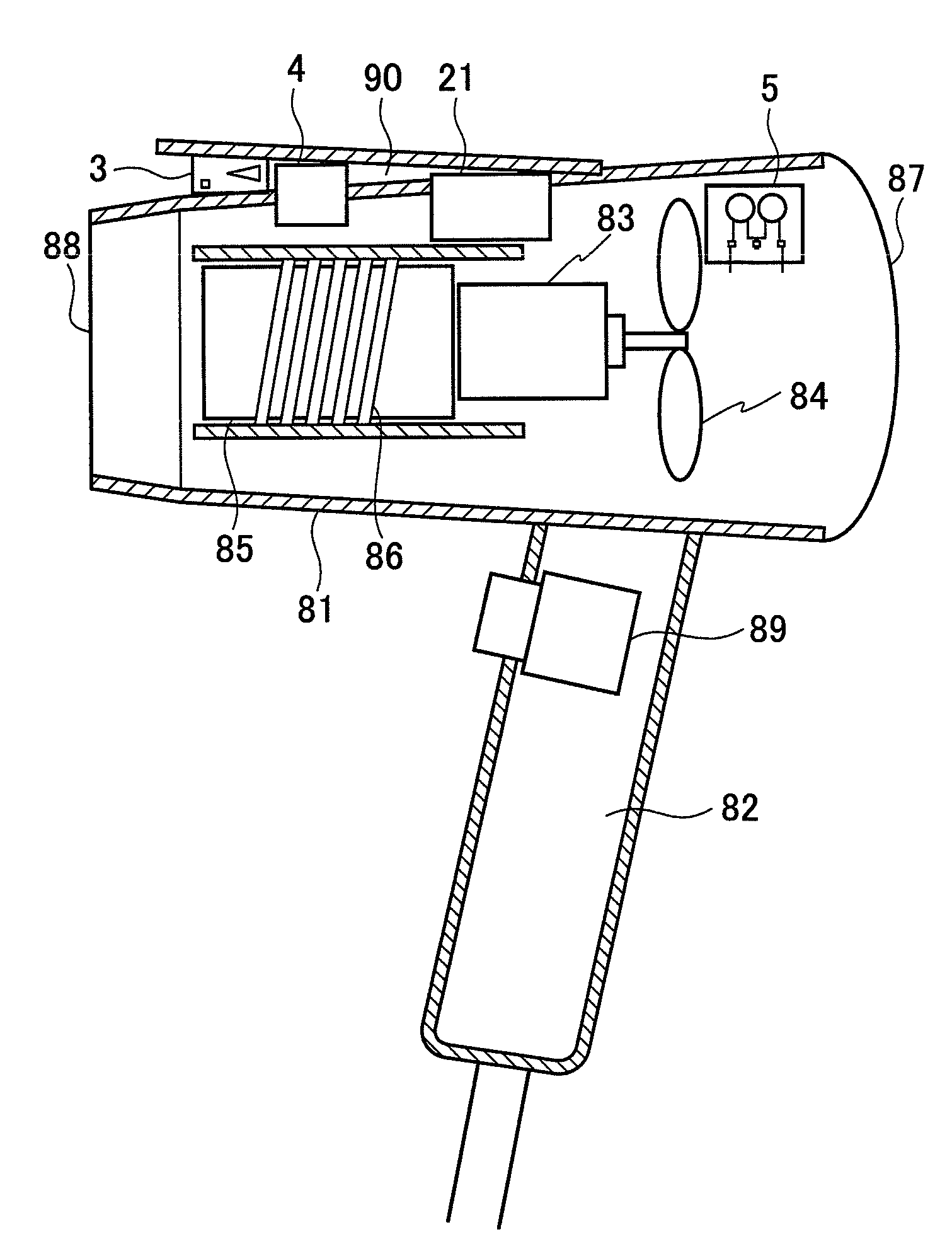
[0047]FIG. 8 is a schematic diagram of a structure of a hair dryer, which is an example of a hot air blower according to a third embodiment of the present invention provided with the electrostatic atomizer shown in FIG. 1 or FIG. 7.

[0048]With reference to FIG. 8, the hair dryer has a housing 81 that forms a main unit, and also has a handle 82 that is integral with the housing 81 and provided on a lower wall of the housing 81 so as to protrude downward. In the housing 81, provided are a fan 84 for intake of air from an air intake port 87, and a motor 83 for rotating the fan 84. At a downstream side of the motor 83, a heating unit 85 is provided on which a heater 86 is disposed to selectively heat the air delivered by the fan 84 and generate warm air when the heater 86 is selectively electrically charged, where the generated warm air is sent through a blow-out port 88 to the outside.

[0049]On the handle 82, a switch 89 is provided which switches on / off the motor 83, the heater 86, and ...


PUM


Abstract

There is provided an electrostatic atomizer that electrostatically atomizes a liquid supplied to a discharge electrode by electric discharge caused by an electric field formed in response to voltage application to the discharge electrode. The electrostatic atomizer has a high-voltage generation circuit that generates a pulse voltage to be applied to the discharge electrode, and the high-voltage generation circuit includes a high-voltage control circuit that converts an input AC signal to a pulse signal, and an igniter that steps up the pulse signal obtained by the high-voltage control circuit to a voltage value of the pulse voltage to be applied to the discharge electrode.

Description

CROSS REFERENCE TO RELATED APPLICATION[0001]This application is based upon and claims the benefit of priority from a Japanese Patent Application No. TOKUGAN 2007-245170, filed on Sep. 21, 2007; the entire contents of which are incorporated herein by reference.BACKGROUND OF THE INVENTION[0002]1. Field of the Invention[0003]The present invention relates to an electrostatic atomizer that produces charged liquid particles, and also to a hot air blower provided with the electrostatic atomizer and an air blowing unit that delivers heated air.[0004]2. Description of the Related Art[0005]As conventional devices of this kind, there has been known a device disclosed in Japanese Patent Application Laid-Open No. 11-300975. According to the technology adopted for a liquid atomizer disclosed in the patent application, the liquid atomizer has an emitting electrode submerged in liquid and a counter electrode disposed opposite to the emitting electrode outside the liquid, and by supplying a pulse vo...

Claims


Application Information

Patent Timeline
Patent Type & Authority Applications(United States)
IPC IPC(8): B05B5/00A45D20/10
CPCA45D20/12B05B5/10B05B5/007B05B5/001B05B5/025
Inventor NAKASONE, HIDETOSHISAIDA, ITARUMIYATA, HIROMITSU
Owner MATSUSHITA ELECTRIC WORKS LTD
Why Eureka
Try Eureka