Turbojet for aircraft, aircraft equipped with such a turbojet, and method for mounting such a turbojet on an aircraft

Inactive Publication Date: 2009-03-26
AIRBUS OPERATIONS (SAS)
View PDF10 Cites 2 Cited by
  • Summary
  • Abstract
  • Description
  • Claims
  • Application Information

AI Technical Summary

Benefits of technology

[0010]One object of the disclosed embodiments is thus to provide a system for fastening an aft jet engine in an upper aft position of the fuselage of an aircraft, in which the impact of this system on the aerodynamic drag is low. Another object of the disclosed embodiments is to provide such a fastening system having a reduced mass in relation to the fastening system of the prior art. An additional object of the disclosed embodiments is to facilitate the mounting and assembly of an aft jet engine and a vertical stabilizer in an upper aft position of the fuselage of an aircraft.
[0011]To achieve this result, the disclosed embodiments provide that one or more stabilizers of an aircraft be integrated with an engine intended to be mounted in the upper aft section of the fuselage of said aircraft. Thus, it is no longer the fuselage that supports the stabilizers but the engine itself. The engine and the stabilizer(s) fastened securely to the structure of the engine form an integrated or one-piece system. This integrated system can then be fastened as a single unit to the fuselage of the aircraft. It is thus possible to reduce the number of supporting structures on the aft section of the fuselage, since only the engine is fastened to the fuselage, the stabilizer(s) being simply connected to the fuselage via their engine fastenings. By partly eliminating the stabilizer supporting structures around the engine, it is also possible to reduce the aerodynamic drag at this point. Indeed, up until now, the engine was surrounded by bulky supporting structures connecting the vertical stabilizer to the aircraft, thus increasing the overall size of the engine / stabilizer module.
[0012]Advantageously, the integrated system according to the disclosed embodiments also comprises one or more of the auxiliary devices required for the operation of the engine that are conventionally fastened to the aft section of the fuselage, close to the engine. For example, the integrated system according to the disclosed embodiments comprises the air-conditioning device of the engine, and some or all of the piping which carries the fluids supplying the engine. By fastening the largest number of equipment items that are useful to the engine, no longer on the fuselage but directly on the engine itself, it is possible to eliminate a commensurate number of independent supporting structures around the aft engine. Moreover, the operation of mounting the engine and the auxiliary devices is facilitated, since they are mounted and fastened as a single unit on the fuselage. It is thus possible to reduce the risks of mounting errors and the time required for said mounting.

Problems solved by technology

Thus, it is no longer the fuselage that supports the stabilizers but the engine itself.
Indeed, up until now, the engine was surrounded by bulky supporting structures connecting the vertical stabilizer to the aircraft, thus increasing the overall size of the engine / stabilizer module.

Method used


Image

  • Turbojet for aircraft, aircraft equipped with such a turbojet, and method for mounting such a turbojet on an aircraft
  • Turbojet for aircraft, aircraft equipped with such a turbojet, and method for mounting such a turbojet on an aircraft

Examples


Embodiment Construction

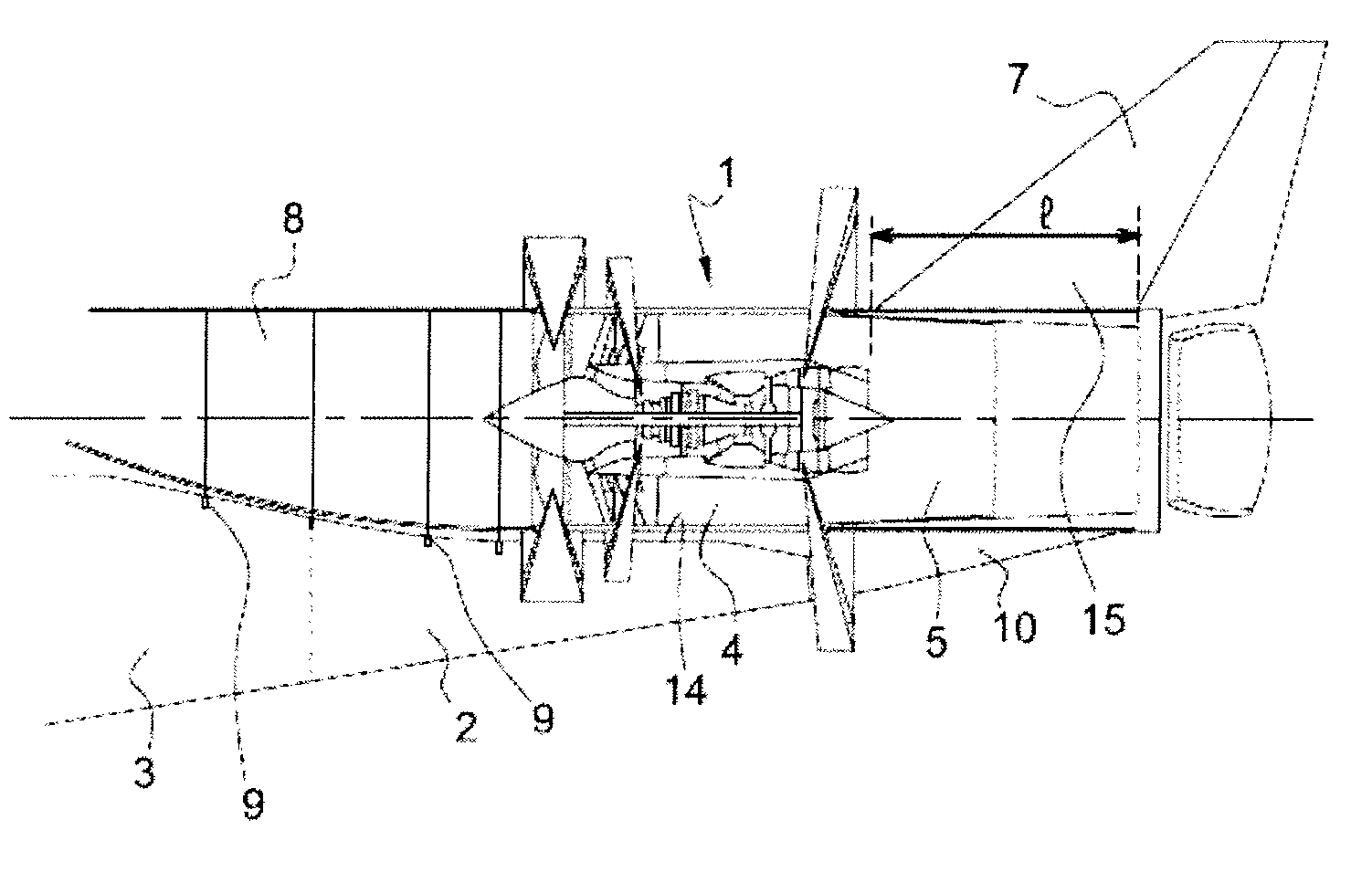
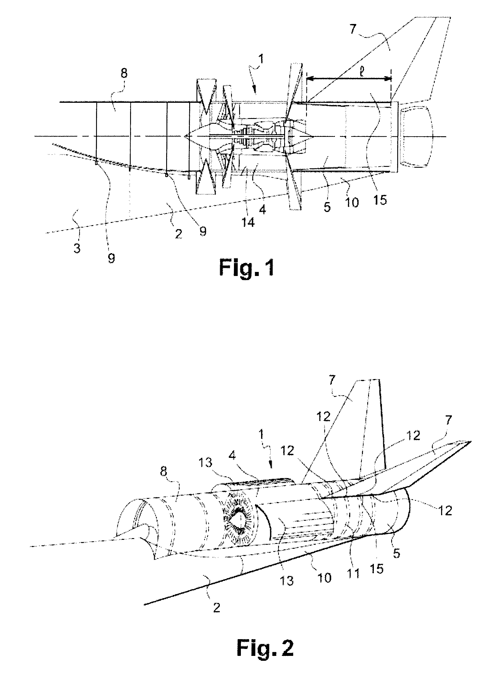
[0034]FIG. 1 shows a jet engine 1 mounted on an aft section 2 of an aircraft fuselage 3. In a general manner, the terms “front” and “rear / aft” are to be understood with respect to the direction of forward travel of the aircraft provided with the jet engine 1.

[0035]The jet engine 1 is mounted in cantilever fashion on the aft section 2 of the fuselage 3. A front section 4 of the jet engine 1 is fastened securely to the aft section 2 of the fuselage 3, while an aft section 5 of said jet engine 1 extends in continuation of the fuselage 3, beyond the aft section 2. The front section 4 of the jet engine 1 can be provided with attachment points connecting said front section 4 of the jet engine 1 of the fuselage 3. The aft section 5, or nozzle, of the jet engine 1 is not fastened to the fuselage 3. In another exemplary embodiment, it is possible to mount the jet engine 1 on the fuselage 3 such that the front section 4 and the aft section 5 are supported by the aft section 2 of the fuselage ...


PUM


Abstract

The disclosed embodiments relates to a jet engine for an aircraft, characterized in that it bears at least one stabilizer, the stabilizer being fastened on the rigid structure of said jet engine so as to form a one-piece assembly. The jet engine can also bear one or more auxiliary devices required for the operation of the jet engine. The disclosed embodiments also relates to an aircraft provided with such a jet engine, and to a method of mounting such a jet engine on an aircraft.

Description

CROSS-REFERENCE TO RELATED APPLICATIONS[0001]This application is the National Stage of International Application No. PCT / FR2006 / 050841, International Filing Date, 2006 Sep. 5, which designated the United States of America, and which international application was published under PCT Article 21(2) as WO Publication No. WO 2007 / 034094 and which claims the benefit of and priority from French Application No. 0552830, filed 2005 Sep. 23, the disclosures of which are incorporated herein by reference in their entirety.BACKGROUND[0002]1. Field[0003]The disclosed embodiments relate to a jet engine for an aircraft. More specifically, the disclosed embodiments relate to a jet engine intended to be mounted in an aft position on the fuselage of an aircraft. The disclosed embodiments also relate to a way of mounting the jet engine on an aircraft.[0004]The disclosed embodiments can generally be applied in the aeronautical field and, more particularly, to supersonic aircraft, the fuselage diameter o...

Claims


Application Information

Patent Timeline
IPC IPC(8): B64D27/20B64D27/16
CPCB64D27/02Y02T50/44B64D27/20Y02T50/40
Inventor GUERING, BERNARDTEULOU, OLIVIER
Owner AIRBUS OPERATIONS (SAS)
Why Eureka
Try Eureka