

Condenser Lens and Optical Scanning Device
a condenser lens and optical scanning technology, applied in optics, instruments, electrical equipment, etc., can solve the problems of small radius of curvature and difficulty in manufacturing fresnel lenses b>1/b>′′, and achieve the effect of superior condensing efficiency and suitable mass production
- Summary
- Abstract
- Description
- Claims
- Application Information
AI Technical Summary
Benefits of technology
Problems solved by technology
Method used
Image

Examples
first embodiment
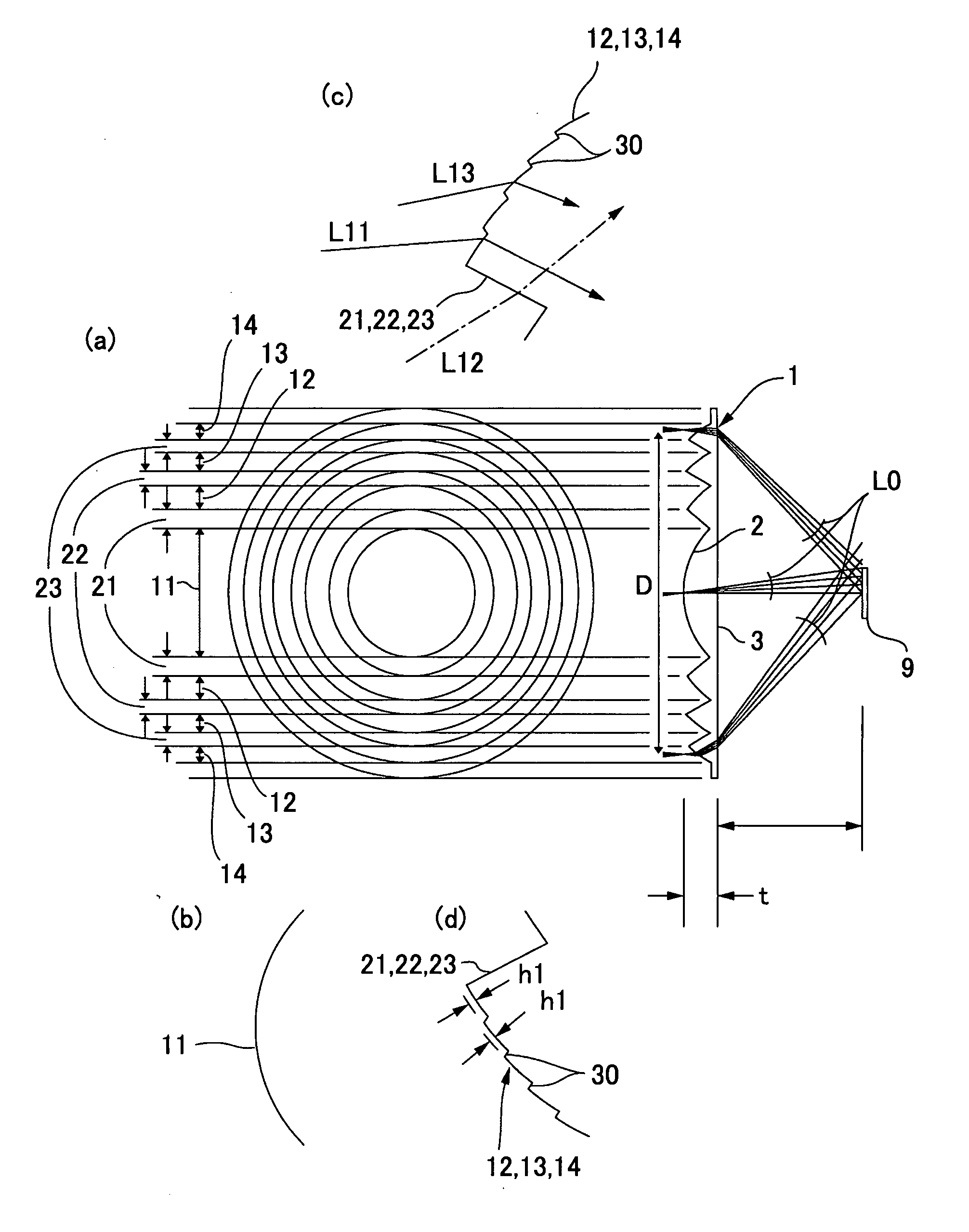
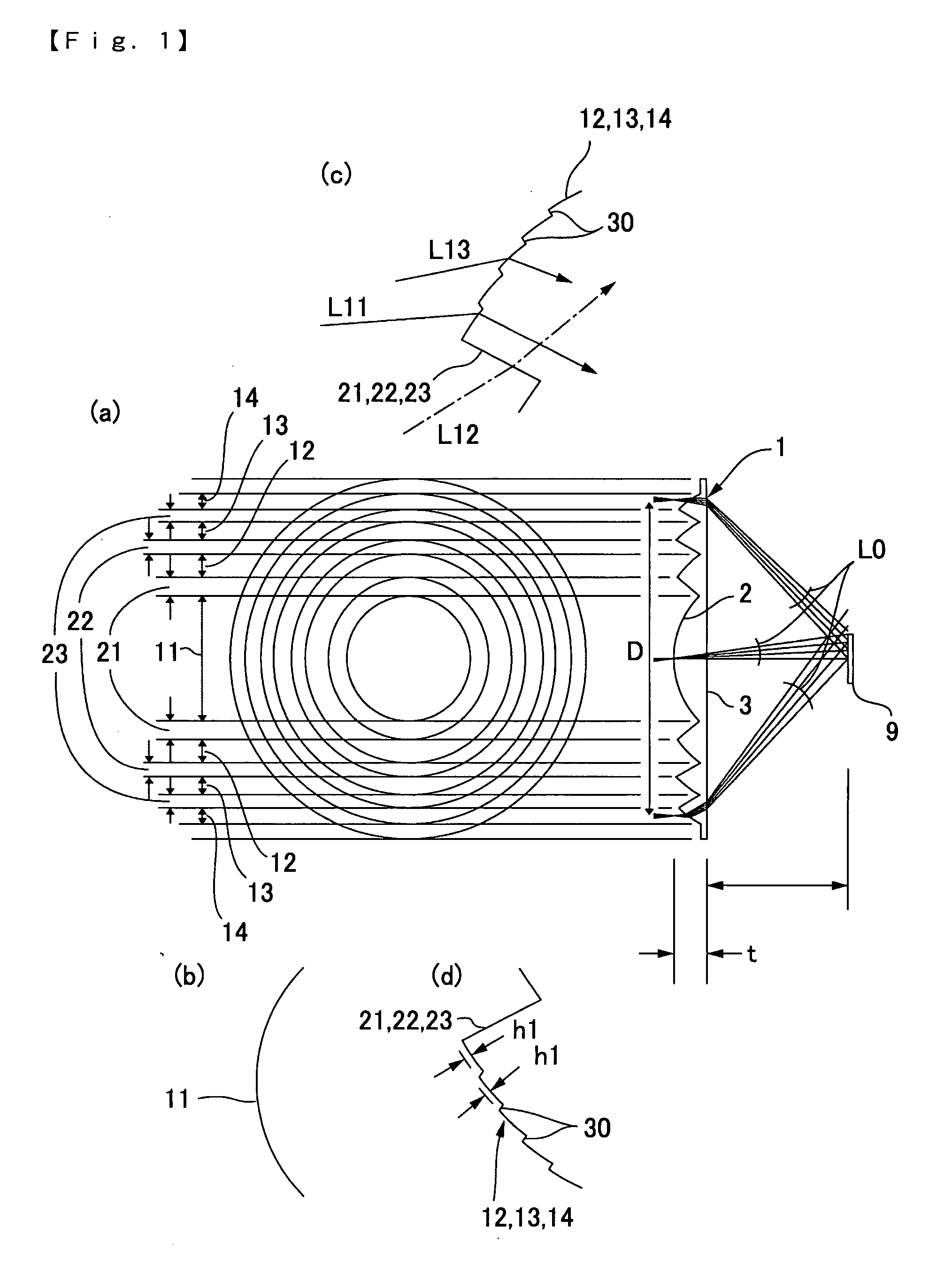
[0049]FIGS. 1(a), 1(b), 1(c) and 1(d) are respectively an explanatory view showing a structure of a condenser lens in accordance with the present invention, an enlarged explanatory view showing its center region, an enlarged explanatory view showing an outer peripheral side region, and an enlarged explanatory view showing another outer peripheral side region.
[0050]A condenser lens 1 shown in FIGS. 1(a), 1(b), 1(c) and 1(d) is a lens made of resin for converging a light beam, which is a scanning light beam emitted from a beam scanning device and reflected by an object to be irradiated, on a photo-detector 9. In the condenser lens 1, a plurality of divided lens faces 11, 12, 13 and 14 in a Fresnel-lens shape is formed on a light incidence face 2 by forming concentric circular grooves 21, 22 and 23. On the other hand, a light emitting face 3 is formed in a simple flat face or a simple curved face.
[0051]The plurality of divided lens faces 11, 12, 13 and 14 includes a diffraction lens fa...
second embodiment
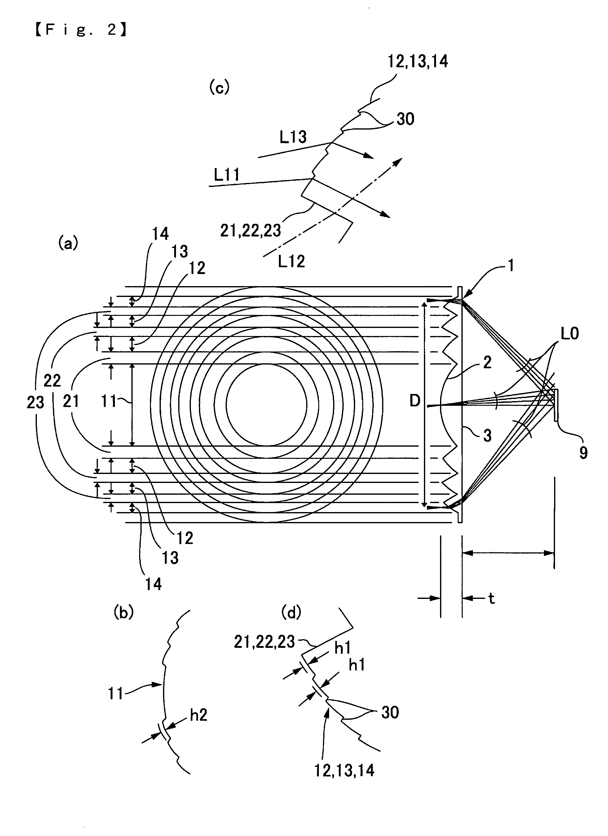
[0114]In the second embodiment, all of a plurality of divided lens faces 11, 12, 13 and 14 are formed in a diffraction lens face where a plurality of steps 30 is formed in a concentrically circular shape.
[0115]In this embodiment, a pitch of the step 30 is 4.5 times or more of heights “h1” and “h2” of the step 30 which are defined as the following expressions;
h1=mA / (n−1)
h2=mA / (n−1)
[0116]wherein “m” denotes order of diffraction, “λ” denotes wavelength, and “n” denotes index of refraction of the lens material.
[0117]Further, in this embodiment, both of refracting power and diffracting power in the plurality of divided lens faces 11, 12, 13 and 14 (diffraction lens face) have positive power.
[0118]Further, the plurality of divided lens faces 11, 12, 13 and 14 are provides with, for example, different lens shapes from each other. In this embodiment, the plurality of divided lens faces 11, 12, 13 and 14 are provided with different aspherical surfaces from each other as shown by an example o...
third embodiment
[0180]In the third embodiment, a pitch of the step 30 is 4.5 times or more of a height “h” of the step 30, which is defined as the following expression;
h=mλ / (n−1)
[0181]wherein “m” denotes order of diffraction, “A” denotes wavelength, and “n” denotes index of refraction of the lens material. Further, both of refracting power and diffracting power in the plurality of divided lens faces 11, 12 and 13 (diffraction lens face) have positive power.
[0182]Lens design data of the condenser lens 1 in this embodiment are, for example, shown as follows.
Divided lens face 11 (diffraction lens face)
[0183]Circular zone region 111[0184]Radius (mm)=0-2.0[0185]Y radius of curvature (R)=infinity[0186]Conic constant (k)=0[0187]The fourth coefficient (A-4)=0[0188]The sixth coefficient (A-6)=0[0189]The eighth coefficient (A-8)=0[0190]The tenth coefficient (A-10)=0[0191]Order of diffraction=3[0192]Optical path difference function RA2=−10.473285[0193]Optical path difference function RA4=0.008546799[0194]Opti...
PUM
 Abstract
Description
Claims
Application Information