Imaging position analyzing method

a position analysis and imaging position technology, applied in the field of imaging position analysis, can solve the problems of insufficient positioning accuracy of the imaging position of the image, insufficient accuracy for various analyses based on image data, and insufficient consideration of positioning accuracy, so as to improve the positioning accuracy of the imaging position, improve the positioning accuracy, and improve the effect of positioning accuracy

Active Publication Date: 2009-03-26
GEO TECHN LAB
View PDF8 Cites 59 Cited by
  • Summary
  • Abstract
  • Description
  • Claims
  • Application Information

AI Technical Summary

Benefits of technology

[0016]It is desirable to further record reference position information in correlation to the image data, where the reference position information represents a time point of reaching a preset reference position, for example, a preset intersection, during imaging. The analyzing device can thus identify an imaging position at an imaging time corresponding to the reference position information (hereafter this imaging position is referred to as ‘reference position’). This enables initialization of at least a location along the moving direction in the course of the analysis based on this reference position information, thus desirably enhancing the positioning accuracy of the imaging position.
[0017]The reference position information may be used in various applications. In one application, frames are sequentially arranged in the imaging order from the reference position as the starting point. Namely the frames are located in time series along the moving direction during imaging. In another application, frames are sequentially arranged in reverse to the imaging order from the reference position as the starting point. Namely the frames are located in reverse to the time series, that is, in a reverse direction opposed to the moving direction during imaging. In both of these applications of frame arrangement, the frame closer to the starting point has the higher positioning accuracy.
[0018]In a navigation system, captured frame images or graphics generated according to the captured frame images may be displayed according to the varying position of the traveling vehicle. In the latter application of arranging the frames in reverse to the time series from the reference position as the starting point, the captured image has the higher position accuracy when the vehicle moves closer to the reference position. Since the vehicle frequently stops and turns at intersections, it is preferable to increase the position accuracy of the captured image at the location closer to an intersection used as the reference position. The latter application is thus especially effective for generation of navigation data.

Problems solved by technology

These prior techniques, however, have rather insufficient positioning accuracy of the imaging position of the image.
The techniques disclosed in Patent Documents 2 and 3 improve the positioning accuracy of the vehicle in its moving direction but do not sufficiently take into account the positioning accuracy in a perpendicular direction intersecting with the moving direction.
The position detected by the GPS includes an error of several ten meters and does not have a sufficient accuracy for various analyses based on the image data.
The position detected by the gyroscope also has only an insufficient accuracy.
The time data of the GPS also includes an error.
Even minimization of the error in position detection accordingly does not allow perfect synchronization with the corresponding captured image.
The imaging position of the image is thus not identifiable with a sufficient accuracy.
Even improvement in accuracy of position detection by the GPS does not ensure the position detected by the GPS during traveling represents the imaging position with a sufficient accuracy.
The low accuracy of the imaging positions does not allow effective analysis of even high-resolution image data.
The inaccurate analysis of the imaging positions leads to failure in accurate identification of the shapes and the positions of road indications, road signs, and building constructions included in the captured image, which is essential for generation of reliable map data.
In the case of image composition by the technique disclosed in Patent Document 1, the low accuracy of the imaging positions causes a positional misalignment between multiple frame images.

Method used


Image

  • Imaging position analyzing method
  • Imaging position analyzing method
  • Imaging position analyzing method

Examples


Embodiment Construction

[0026]Some modes of carrying out the invention are described below in the following sequence:

[0027]A. System Configuration

[0028]B. Data Structure

[0029]C. Principle of Imaging Position Analysis[0030]C-1. Initial Path[0031]C-2. Feature Point Tracking Process

[0032]D. Imaging Position Analyzing Process

[0033]E. Sign / Indication Extraction Process

[0034]F. Concrete Examples

[0035]G1. Modified Example: Arrangement of Frame Data

[0036]G2. Modified Example: Utilization of Side Image

[0037]G3. Modified Example: Detection of Time Change

[0038]G4. Modified Example: Analysis of Guide Plate Position Coordinates

A. SYSTEM CONFIGURATION

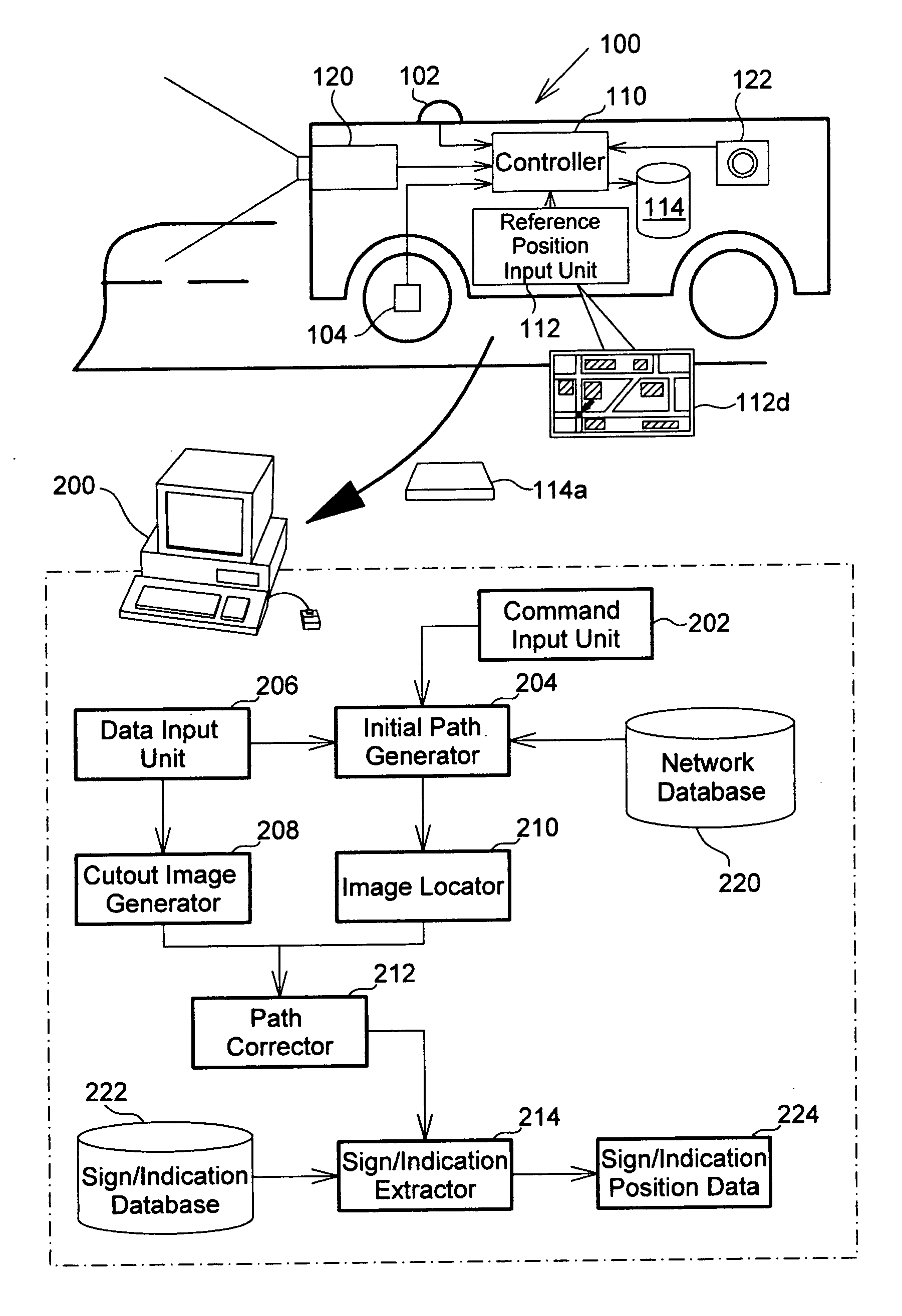
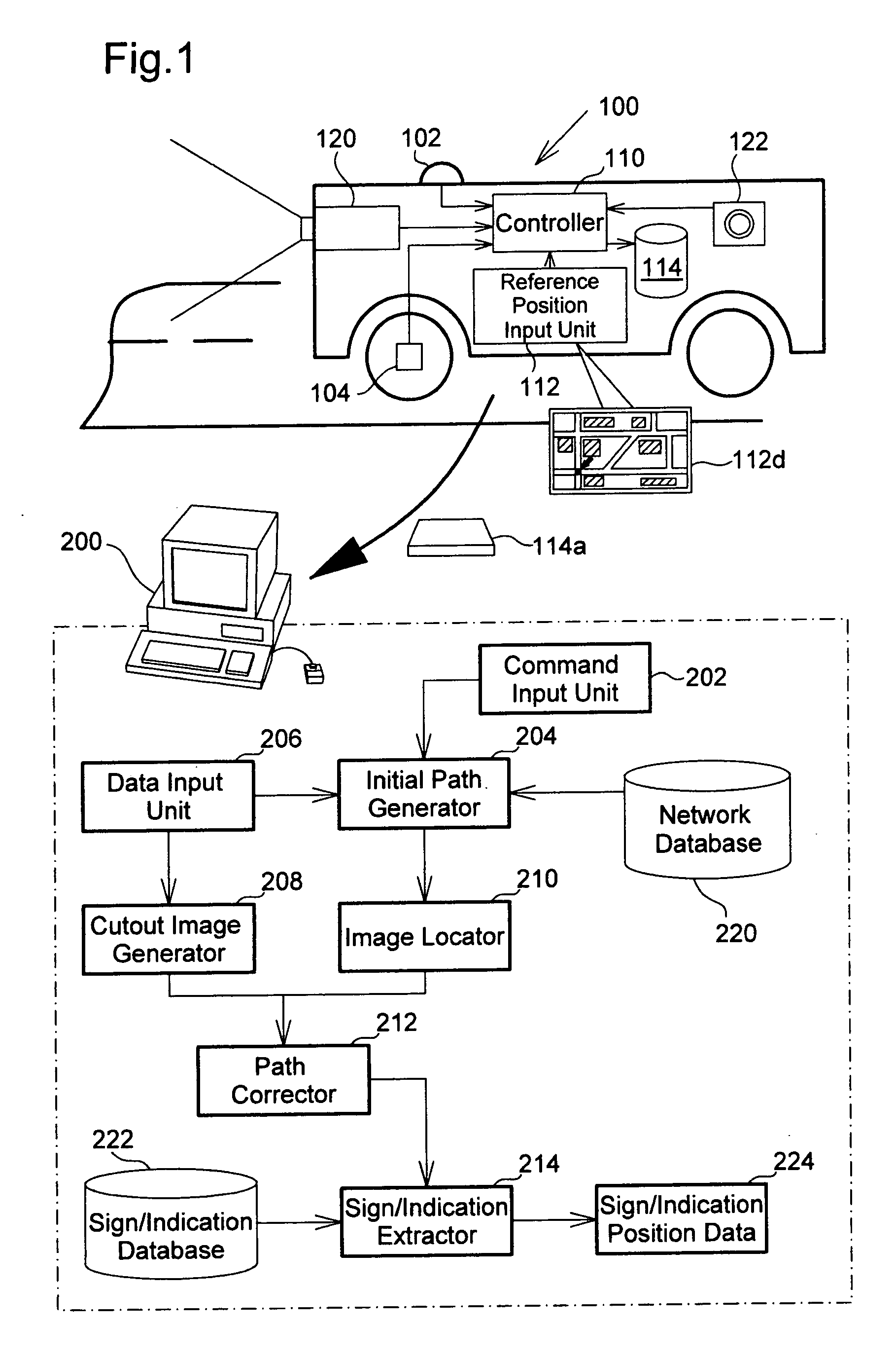
[0039]FIG. 1 schematically illustrates the configuration of an image data processing system in one embodiment of the invention. The image data processing system processes a moving image captured by a traveling vehicle on the road. The series of processing performed by the image data processing system includes an imaging position analyzing process that analyzes and specifies...


PUM


Abstract

The imaging position of each of the frames in image data of a plurality of frames captured while a vehicle is traveling is accurately determined.
An image data acquiring device (100) captures a front image by means of a video camera (120) while a vehicle is traveling. When in imaging, the device associates the vehicle speed pulse detected by a vehicle speed sensor (104) with the frame data and records them. An image data processing device (200) arranges data on each frame of the image along the initial path according to the correspondence with the vehicle speed pulse. The device determines the variation between the frames of a feature point such as a road lane marking included in the image, reflects the variation on the initial path, and corrects the errors in the direction perpendicular to the moving direction so as to determine the traveling path and imaging positions of the frames.
With this, the accuracy in determining the imaging position of each frame is improved.

Description

TECHNICAL FIELD[0001]The present invention relates to a technique of analyzing the imaging position of each of multiple frames constituting an image, for example, a moving image, captured by a traveling vehicle.BACKGROUND ART[0002]Various applications have been proposed for images captured with a video camera mounted on a vehicle. For example, information on these captured images is utilized for generation of electronic map data, which provides a three-dimensional map reproducing the town as a three-dimensional image based on computer graphics. The technique disclosed in Japanese Patent Laid-Open No. H07-37065 (Patent Document 1) combines multiple frame images captured with a video camera and generates one composite image covering a wide area. The generated composite image may be utilized for monitoring, for example, the status of the railway track or the status of the power cable.[0003]For such applications of the images captured with the video camera, it is essential to accurately...

Claims


Application Information

Patent Timeline
Patent Type & Authority Applications(United States)
IPC IPC(8): G06K9/00
CPCG01C15/00G01C21/26G06K9/00798G06T2207/30256G06T2207/10016G06T2207/20021G06T2207/30244G06T7/2033G06T7/246G06V20/588G01C21/34G08G1/04G08G1/01
Inventor KISHIKAWA, KIYONARITOU, KOUHEIIRIE, TORU
Owner GEO TECHN LAB
Why Eureka
Try Eureka