System and Method for Use of Fluoroscope and Computed Tomography Registration for Sinuplasty Navigation

a technology of computed tomography and navigation system, which is applied in the field of medical device navigation system and method, can solve the problems of inability to accurately register external markers or headsets using keyboards or mouse, time-consuming and laborious, and improve the accuracy of medical device navigation

Inactive Publication Date: 2009-03-26
GENERAL ELECTRIC CO
View PDF12 Cites 149 Cited by
  • Summary
  • Abstract
  • Description
  • Claims
  • Application Information

AI Technical Summary

Benefits of technology

[0024]Certain embodiments of the present invention provide systems and methods of improved medical device navigation. Certain embodiments include a system for acquiring a first image of a patient anatomy, a second image of patient anatomy, and creating a registered image by utilizing image based registration techniques applied to the first and second images. Other embodiments teach systems and methods for navigating a sinuplasty device within a patient anatomy using one or more registered images.

Problems solved by technology

However, there are some disadvantages with previous registration or correlation techniques.
Identifying fiducials, markers, or a headset using a keyboard or mouse may be time consuming.
In addition, the registration of external markers or a headset may not be as accurate as desired.
By contrast, fluoroscopic views may be distorted.
The procedure of correlating the lesser quality and non-planar fluoroscopic images with planes in the 3-D image data sets may be time-consuming.
In techniques that use fiducials or added markers, a surgeon may follow a lengthy initialization protocol or a slow and computationally intensive procedure to identify and correlate markers between various sets of images.
Correlation of patient anatomy or intraoperative fluoroscopic images with precompiled 3-D diagnostic image data sets may also be complicated by intervening movement of the imaged structures, particularly soft tissue structures, between the times of original imaging and the intraoperative imaging procedure.
In cases where differing patient positioning or a changing tissue characteristic like a growing tumor actually changes the tissue dimension or position between imaging sessions, further confounding factors may appear.
However, registration using a reference unit located on the patient and away from the fluoroscope camera introduces inaccuracies into coordinate registration due to distance between the reference unit and the fluoroscope.
Additionally, the reference unit located on the patient is typically small or else the unit may interfere with image scanning.
A smaller reference unit may produce less accurate positional measurements, and thus impact registration.

Method used


Image

  • System and Method for Use of Fluoroscope and Computed Tomography Registration for Sinuplasty Navigation
  • System and Method for Use of Fluoroscope and Computed Tomography Registration for Sinuplasty Navigation
  • System and Method for Use of Fluoroscope and Computed Tomography Registration for Sinuplasty Navigation

Examples


Embodiment Construction

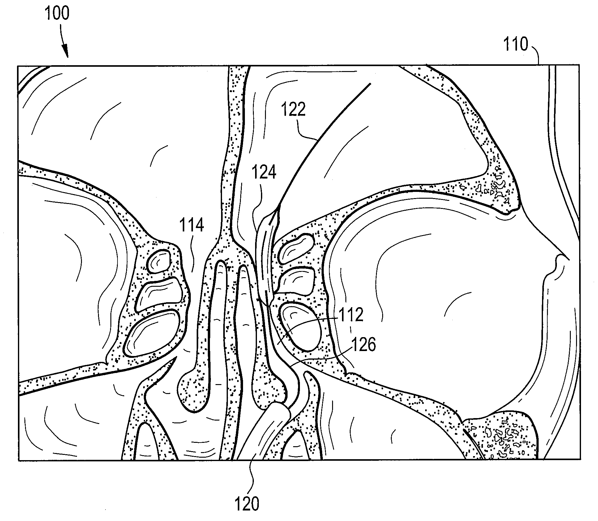
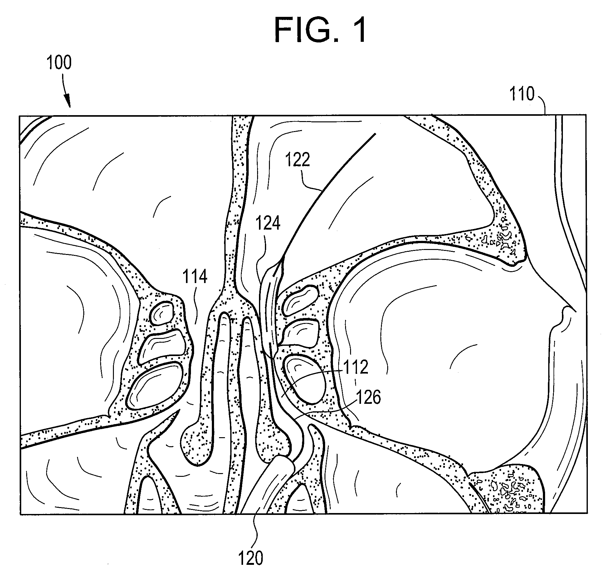
[0033]FIG. 1 illustrates an exemplary sinuplasty system 100 as used in accordance with an embodiment of the present invention. The sinuplasty system 100 includes a sinuplasty device 120, a guide wire 122, catheter balloon 124, and cannula 126. The sinuplasty system 100 illustrated in FIG. 1 is located inside the cranial region 110 of a patient. The patient's cranial region 110 further includes a sinus passageway 112 and a sinus passageway 114. More specifically, the sinuplasty device 120 is located in the patient's sinus passageway 112. A sinus passageway may also be known as an ostium. The sinuplasty device 120 contains several components, including the guide wire 122, the catheter balloon 124, and the cannula 126.

[0034]Sinuplasty is a medical procedure utilizing a device to enlarge a sinus passageway of a patient. More specifically, as illustrated in the simplified example of FIG. 1, the sinuplasty device 120 is inserted into the cranial region 110 of a patient. The sinuplasty dev...


PUM


Abstract

Certain embodiments of the present invention provide systems and methods of improved medical device navigation. Certain embodiments include acquiring a first image of a patient anatomy, a second image of patient anatomy, and creating a registered image based on the first and second images. Certain preferred embodiments teach systems and methods of automated image registration without the use of fiducial markers, headsets, or manual registration. Thus the embodiments teach a simplified method of image registration that allows a medical device to be navigated within a patient anatomy. Furthermore, the embodiments teach navigating a medical device in a patient anatomy with reduced exposure to ionizing radiation. Additionally, the improved systems and methods of image registration provide for improved accuracy of the registered images.

Description

BACKGROUND OF THE INVENTION[0001]The present invention generally relates to improved systems and methods for medical device navigation. More particularly, the present invention relates to improved image registration and navigation of a surgical device in a patient anatomy.[0002]Medical practitioners, such as doctors, surgeons, and other medical professionals, often rely upon technology when performing a medical procedure, such as image-guided surgery or examination. A tracking system may provide positioning information for the medical instrument with respect to the patient or a reference coordinate system, for example. A medical practitioner may refer to the tracking system to ascertain the position of the medical instrument when the instrument is not within the practitioner's line of sight. A tracking system may also aid in pre-surgical planning.[0003]The tracking or navigation system allows the medical practitioner to visualize the patient's anatomy and track the position and orie...

Claims


Application Information

Patent Timeline
Patent Type & Authority Applications(United States)
IPC IPC(8): G06K9/62A61F2/958
CPCA61B17/24A61B19/5225A61B2019/5238A61M29/02A61B2019/5289A61B2019/5295A61M25/0662A61B2019/524A61B2090/367A61B2090/364A61B2090/376A61B90/37A61B2090/3762
Inventor BATTLE, VIANNEY P.LEPARMENTIER, RICHARD A.ATRIA, CRISTIANSAMPATHKUMAR, RAGURAMANNODE-LANGLOIS, LAURENT JACQUES
Owner GENERAL ELECTRIC CO
Why Eureka
Try Eureka