Glass furnace flue gas to heat glassmaking material and oxidant

a technology of glass furnace and glassmaking material, which is applied in the field of glass production, can solve the problems of reducing throughput and even plugging of heat exchanger passages, wasting energy in glassmaking operations, and reducing the efficiency of glassmaking operations

Inactive Publication Date: 2009-04-02
PRAXAIR TECH INC
View PDF17 Cites 18 Cited by
  • Summary
  • Abstract
  • Description
  • Claims
  • Application Information

AI Technical Summary

Benefits of technology

[0022]providing one or more controllable dampers that can alter the volumes of said combustion products that are fed to said first heat exchanger and to said second heat exchanger.
[0023]As used herein, that glassmaking material is “adherent” means that when 250 grams of the glassmaking material which is in free-flowing particulate form at room temperature is heated to a given temperature in a metal container made of the same material as the barrier that the material is to flow past and is held at that temperature for 30 minutes and the container is then inverted, at least 1% of the material adheres to the surface of the container; and the temperature at which the material “becomes adherent” is the lowest temperature at which the material is thus “adherent” when it is heated to that temperature.

Problems solved by technology

Even in glassmaking equipment that achieves a relatively high efficiency of heat transfer from the combustion to the glassmaking materials to be melted, the combustion products that exit the melting vessel typically have a temperature well in excess of 2000° F., typically in a range of 2600 to 2950 F., and thus represent a considerable waste of energy that is generated in the glassmaking operations unless that heat energy can be at least partially recovered from the combustion products.
The combustion products that exit the glassmelting furnace typically have a temperature well in excess of 2000° F., typically in a range of 2500 to 2900 F, and thus represent a considerable waste of energy in spite of its reduced volume.
This maximum temperature is imposed by considerations of the capability of the materials from which the heat exchanger is constructed to withstand higher temperatures, and considerations of the tendency of the glassmaking material to begin to soften and become adherent (or “sticky”) if it becomes too hot during the heat exchange step, leading to reduced throughput and even plugging of the heat exchanger passages.
Because of the relatively low temperature of flue gas, however, the maximum preheat temperatures achieved by this method was limited to about 600° F. In addition the physical size of the commercially available batch / cullet preheater is very large in order to exchange heat with the large volume of flue gas, making it economically unattractive.
However, reducing the temperature of this stream of combustion products by adding to it a gaseous diluent such as air, and / or spraying a cooling liquid such as water into the stream, is disadvantageous as such approaches reduce the amount of recoverable heat remaining in the gaseous combustion products, increase the size of the gas handling equipment that is needed, and adds additional equipment and process expense.

Method used


Image

  • Glass furnace flue gas to heat glassmaking material and oxidant
  • Glass furnace flue gas to heat glassmaking material and oxidant
  • Glass furnace flue gas to heat glassmaking material and oxidant

Examples


example

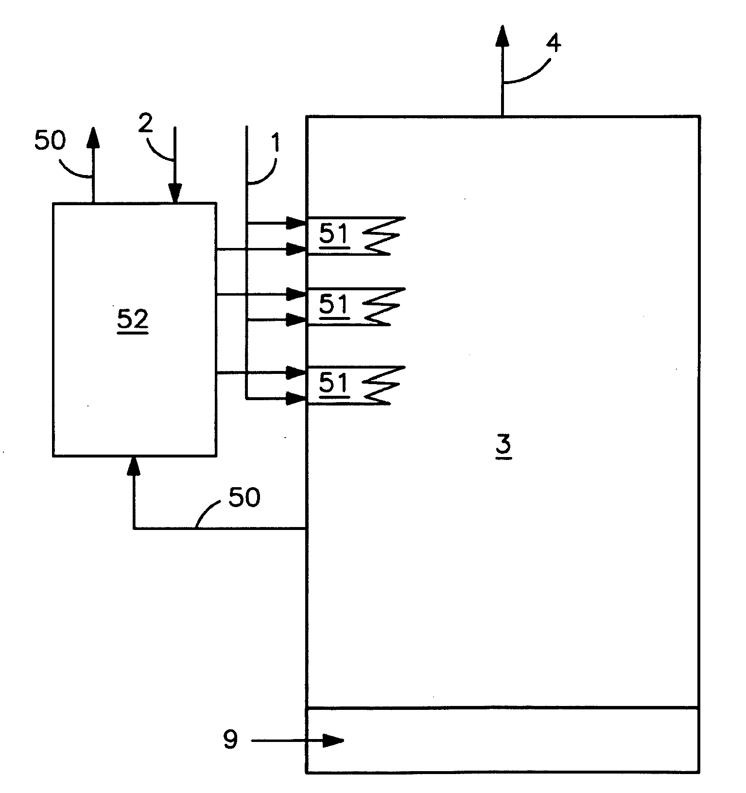
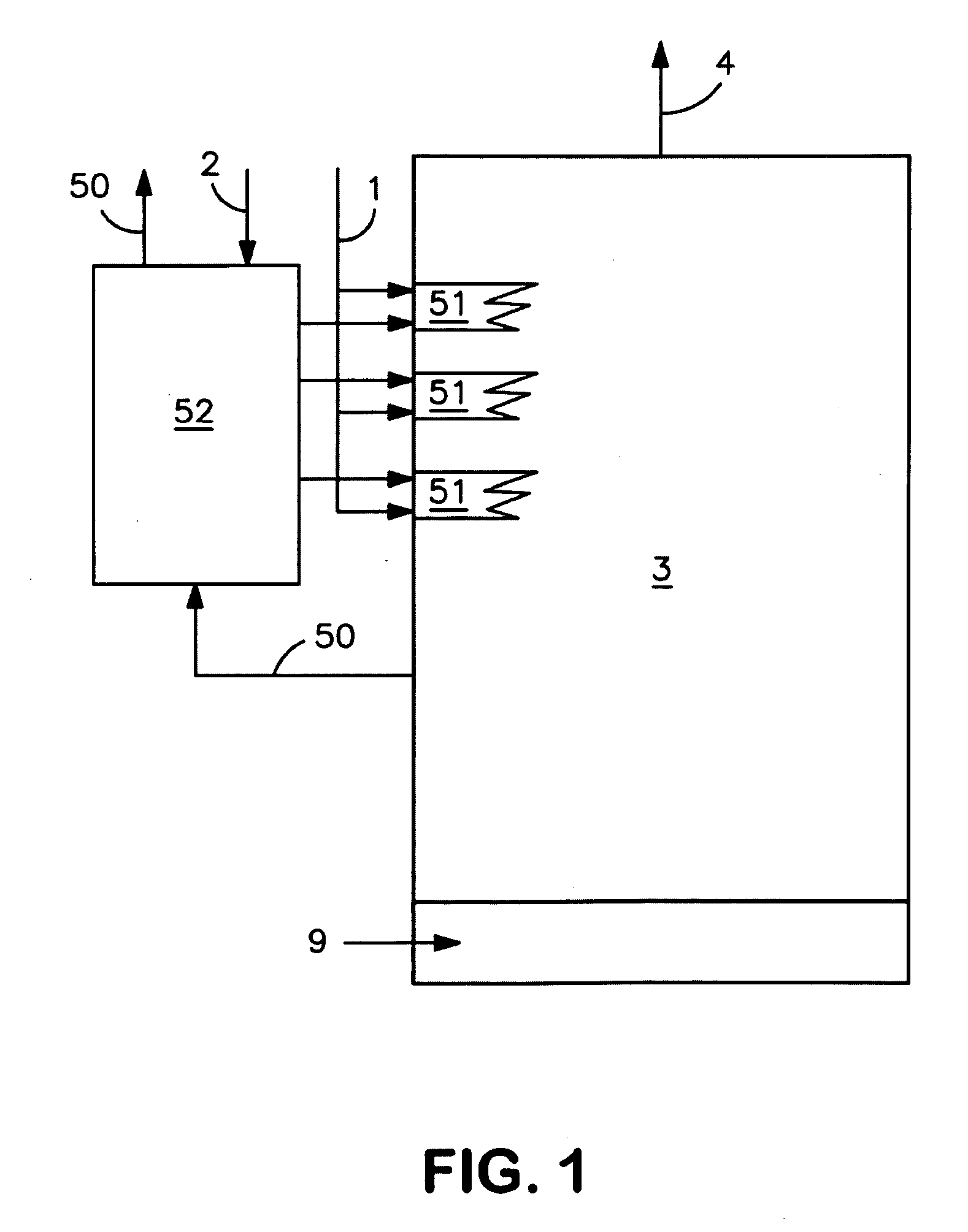
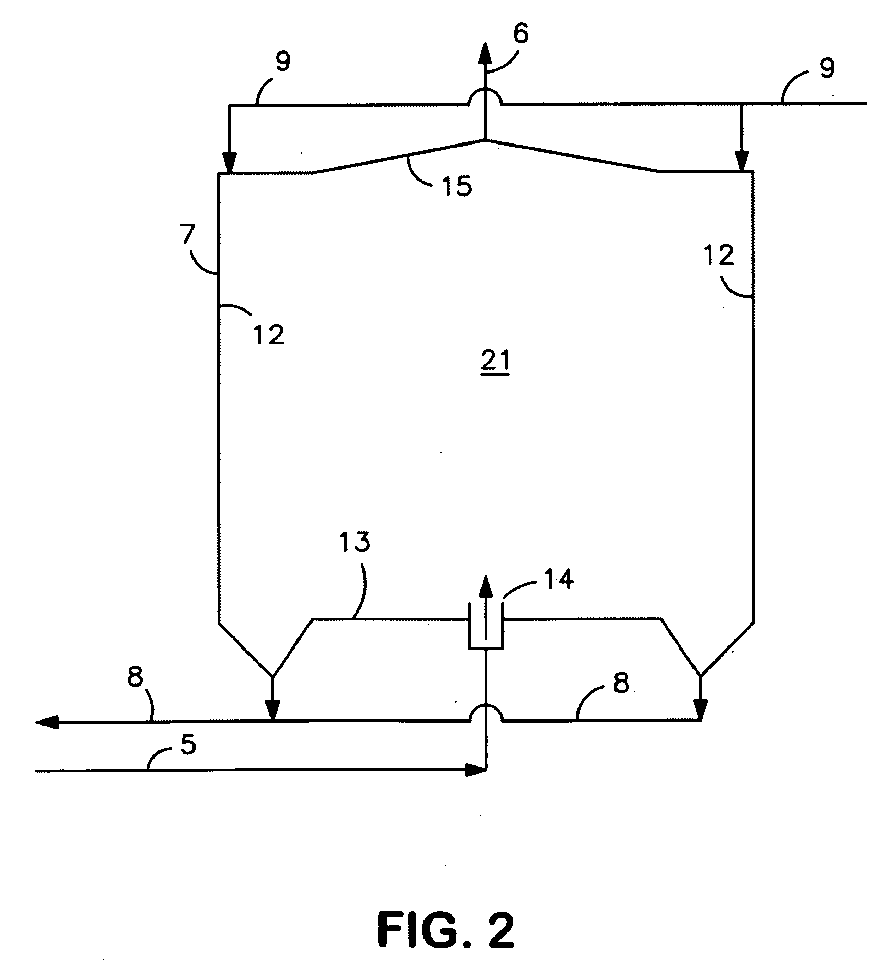
[0069]Table 1 shows an illustrative comparison of the energy balances of (Case 1) 450 short tpd regenerative container glass melting furnace with five ports to a regenerative-type indirect heat exchanger, (Case 2) the same furnace with a conventional batch cullet preheater to preheat batch / cullet to 572° F., and (Case 3) a modified 450 short tpd regenerative container glass melting with the present invention to preheat batch / cullet to 932° F. 50-50 mixture of batch and cullet is assumed in all cases. In Case 3 a portion of the flue gas from the air fired glass melting furnace is extracted and directly introduced into a radiative unit 7 to preheat the glassmaking material, preferably to 600 to 1200 F, and more preferably to 800-1100° F. The remaining flue gas passes through the existing indirect heat exchanger(s) e.g. regenerators or recuperators. The heat recovery efficiency of the regenerators or recuperators is improved as the ratio of the hot flue gas flow rate to the combustion ...


PUM

PropertyMeasurementUnit
temperatureaaaaaaaaaa

Abstract

Heat in a stream of combustion products obtained from a glassmelting furnace heated by oxy-fuel combustion is passed to incoming glassmaking materials in a heat exchanger without requiring reduction of the temperature of the stream yet without causing softening of the glassmaking material.

Description

CROSS-REFERENCE TO RELATED APPLICATION[0001]The present invention claims priority to U.S. provisional patent application Ser. No. 60 / 976,156, filed Sep. 28, 2007, the entire contents of which are incorporated herein by reference in its entirety.FIELD OF THE INVENTION[0002]The present invention relates to the production of glass, and more particularly to the heating of glassmaking material by heat exchange with combustion products (flue gas) formed in the combustion that is carried out to generate heat for melting the glassmaking material.BACKGROUND OF THE INVENTION[0003]Conventional glassmaking methods require establishing in a glassmelting furnace temperatures that are high enough to melt the glassmaking material (by which is meant one or more materials such as sand, soda ash, limestone, dolomite, feldspar, rouge, which are collectively known as “batch” and / or broken, scrap and recycled glass, known as “cullet”). The required high temperature is generally obtained by combustion of ...

Claims


Application Information

Patent Timeline
Patent Type & Authority Applications(United States)
IPC IPC(8): C03B5/16
CPCC03B5/237C03B3/023Y02P40/50Y02P40/57
Inventor KOBAYASHI, HISASHI
Owner PRAXAIR TECH INC
Why Eureka
Try Eureka