Non-invasive fluid density and viscosity measurement

Active Publication Date: 2009-04-02
TRIAD NAT SECURITY LLC
View PDF10 Cites 36 Cited by
  • Summary
  • Abstract
  • Description
  • Claims
  • Application Information

AI Technical Summary

Benefits of technology

[0008]Accordingly, it is an object of the present invention to provide an apparatus and method for determining the density of a fluid without having to divert the fluid from the pipe or cylinder in which the fluid is contained or flowing to a separate U-tube or other device.
[0009]Another object of the invention is to provide an apparatus and method for determining the density and viscosity of a fluid without having to divert the fluid from the pipe or cylinder in which the fluid is contained or flowing to a separate U-tube, or other device.
[0010]Yet another object of the invention is to provide an apparatus and method for noninvasively determining the density and viscosity of a fluid without having to transfer the fluid from the pipe or cylinder in which the fluid is contained or flowing to a separate U-tube or other container.
[0017]Benefits and advantages of the present invention include, but are not limited to, the real-time, noninvasive and continuous monitoring of a fluid flowing through a pipe, while maintaining the integrity of the system in which the fluid is flowing, and without requiring mechanical alterations to the pipe.

Problems solved by technology

This necessitates the undesirable drilling of holes in the pipe, attaching flanges and other modifications of the pipe, all invasive procedures.

Method used


Image

  • Non-invasive fluid density and viscosity measurement
  • Non-invasive fluid density and viscosity measurement
  • Non-invasive fluid density and viscosity measurement

Examples


example 1

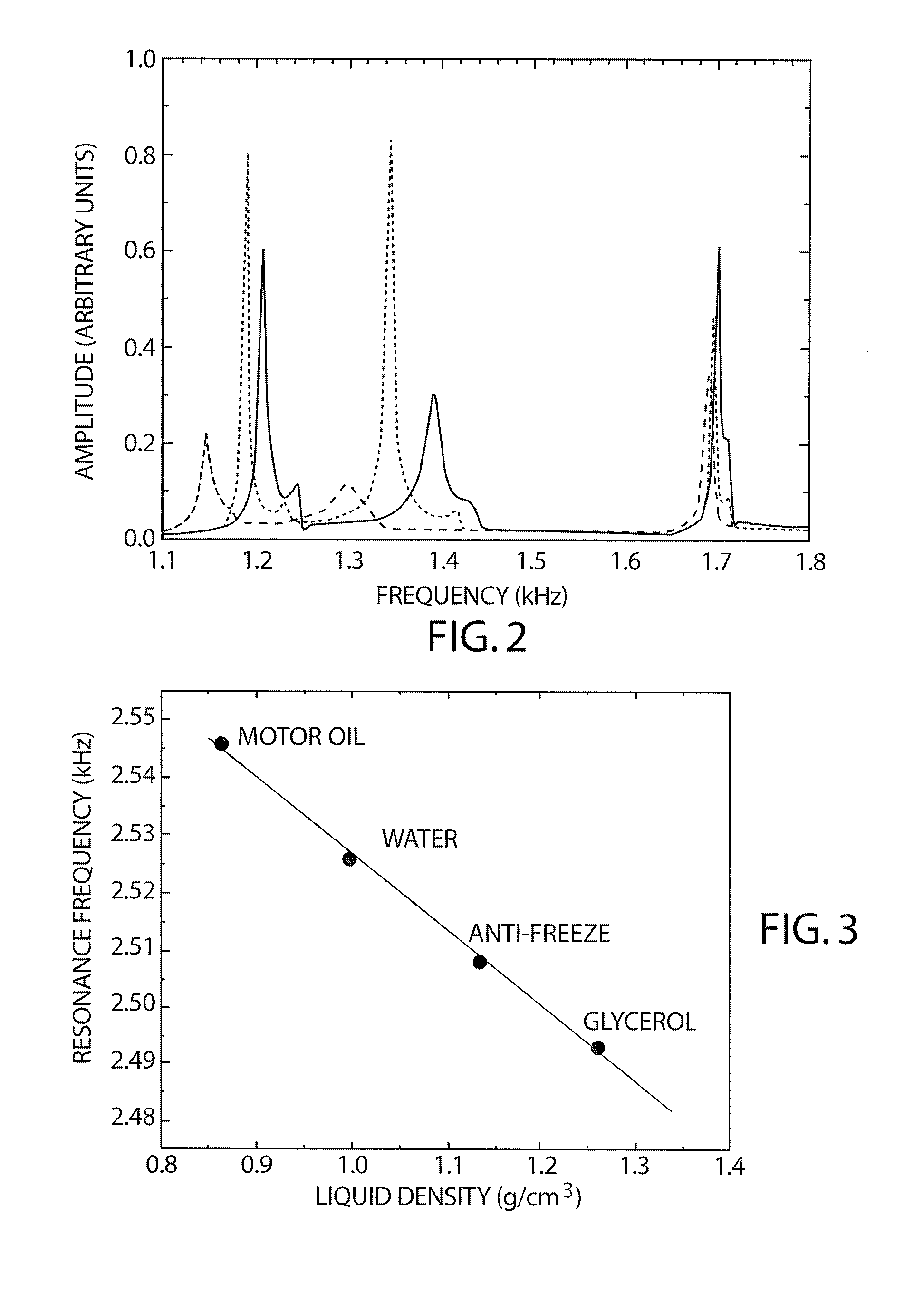
[0032]FIG. 2 is a graph of amplitude of the received vibration signal as a function of frequency for swept frequency vibration excitation applied to the pipe surface between about 1 kHz and about 1.5 kHz. Measurements were made using a 23 cm long section of a 1.8 mm thick, 7.3 cm diameter copper pipe with three fluids: corn syrup (ρ=1.350 g / cm3), water (ρ=0.998 g / cm3) and cooking oil (corn oil ρ=0.922 g / cm3). The vibration modes show clear separation in resonance frequency, but the lower frequency mode showed greater resolution among the resonances and was used for the density measurement. In fact, higher modes may be used, but with different density resolutions. As stated hereinabove, the full-width-at-half-maximum of the peaks is proportional to the viscosity of the fluids.

example 2

[0033]FIG. 3 is a plot of the resonance vibration frequency as a function of fluid density for four fluids: Motor oil 10-30 (ρ=0.863 g / cm3), water (ρ=0.998 g / cm3), ethylene glycol (anti-freeze, ρ=1.136 g / cm3), and glycerol (ρ=1.350 g / cm3), for a steel pipe that has significantly greater wall thickness and is much larger than the one used in the collection of data for FIG. 2 (a 5-mm thick wall, a diameter of 15 cm, and a length of 60 cm). The measured resonance frequencies of the lowest vibration mode of the pipe are shown as dots, and the curve fit to the data with using theory is shown as the solid line. The theoretical form for the equation is the same as that set forth hereinabove for the vibrating tube densitometer, and illustrates that the behavior of the density measurements in a pipe follows the same form. The measured resonance frequency of the empty pipe is 2.7 kHz which is in good agreement with that derived from the curve fit of the data (2.673 kHz).

example 3

[0034]FIG. 4 is a graph of the fluid viscosity plotted as √{square root over (μρfluid)}, as a function of the widths, Δƒ of the first resonances for the fluids shown in FIG. 2 hereof. The experimental data are shown by the black dots, and a plot the equation:

ρfluidμ=0.15+0.112exp(Δf2.254),

using literature values for √{square root over (μρfluid)} fits the experimental data well. As stated hereinabove, the decay time-constants measured in the experiment and the resonance widths are related and provide the same information, one being in the frequency domain and the other in the time domain. The equation parameters are slightly different for the second set of resonance peaks shown in FIG. 2 hereof because of different sensitivity, but the form is the same.

[0035]Thus, attenuation by a fluid in a pipe clearly damps vibration resonance curves. This effect manifests itself in two different ways: (1) the width of the resonance is broadened as the density of the enclosed fluid increases; and ...


PUM

PropertyMeasurementUnit
frequencyaaaaaaaaaa
frequencyaaaaaaaaaa
frequency bandwidthaaaaaaaaaa

Abstract

The noninvasively measurement of the density and viscosity of static or flowing fluids in a section of pipe such that the pipe performs as the sensing apparatus, is described. Measurement of a suitable structural vibration resonance frequency of the pipe and the width of this resonance permits the density and viscosity to be determined, respectively. The viscosity may also be measured by monitoring the decay in time of a vibration resonance in the pipe.

Description

STATEMENT REGARDING FEDERAL RIGHTS[0001]This invention was made with government support under Contract No. DE-AC52-06NA25396 awarded by the U.S. Department of Energy. The government has certain rights in the invention.FIELD OF THE INVENTION[0002]The present invention relates generally to the measurement of density and viscosity of fluids and, more particularly, to the noninvasive measurement of density and viscosity of fluids using acoustic technology.BACKGROUND OF THE INVENTION[0003]Presently, a vibrating U-shaped-tube densitometer, where the natural mechanical frequency of vibration of the fluid-filled tube changes with varying fluid density is widely used to measure fluid density. A fluid is placed inside a vibrating U-tube and its resonance frequency is monitored. This frequency is related to the fluid density. Electromechanical elements and a feed-back loop amplifier maintain the vibrations and provide a frequency output determined by the fluid density. Such measurements requir...

Claims


Application Information

Patent Timeline
Patent Type & Authority Applications(United States)
IPC IPC(8): G01N9/00
CPCG01N11/167G01N9/002
Inventor SINHA, DIPEN N.
Owner TRIAD NAT SECURITY LLC
Why Eureka
Try Eureka