Laser cutting system and method

Inactive Publication Date: 2009-04-02
DEERE & CO
View PDF7 Cites 16 Cited by
  • Summary
  • Abstract
  • Description
  • Claims
  • Application Information

AI Technical Summary

Benefits of technology

[0007]Accordingly, an object of this invention is to provide a system and a method by which certain tolerances on the workpiece are maintained to e

Problems solved by technology

It is found to be disadvantageous that the correction takes place both on the workpiece side and on the laser head side, and consequently a relatively complex control system is used to ensure a certain quality standard in the processin

Method used


Image

  • Laser cutting system and method
  • Laser cutting system and method
  • Laser cutting system and method

Examples


Embodiment Construction

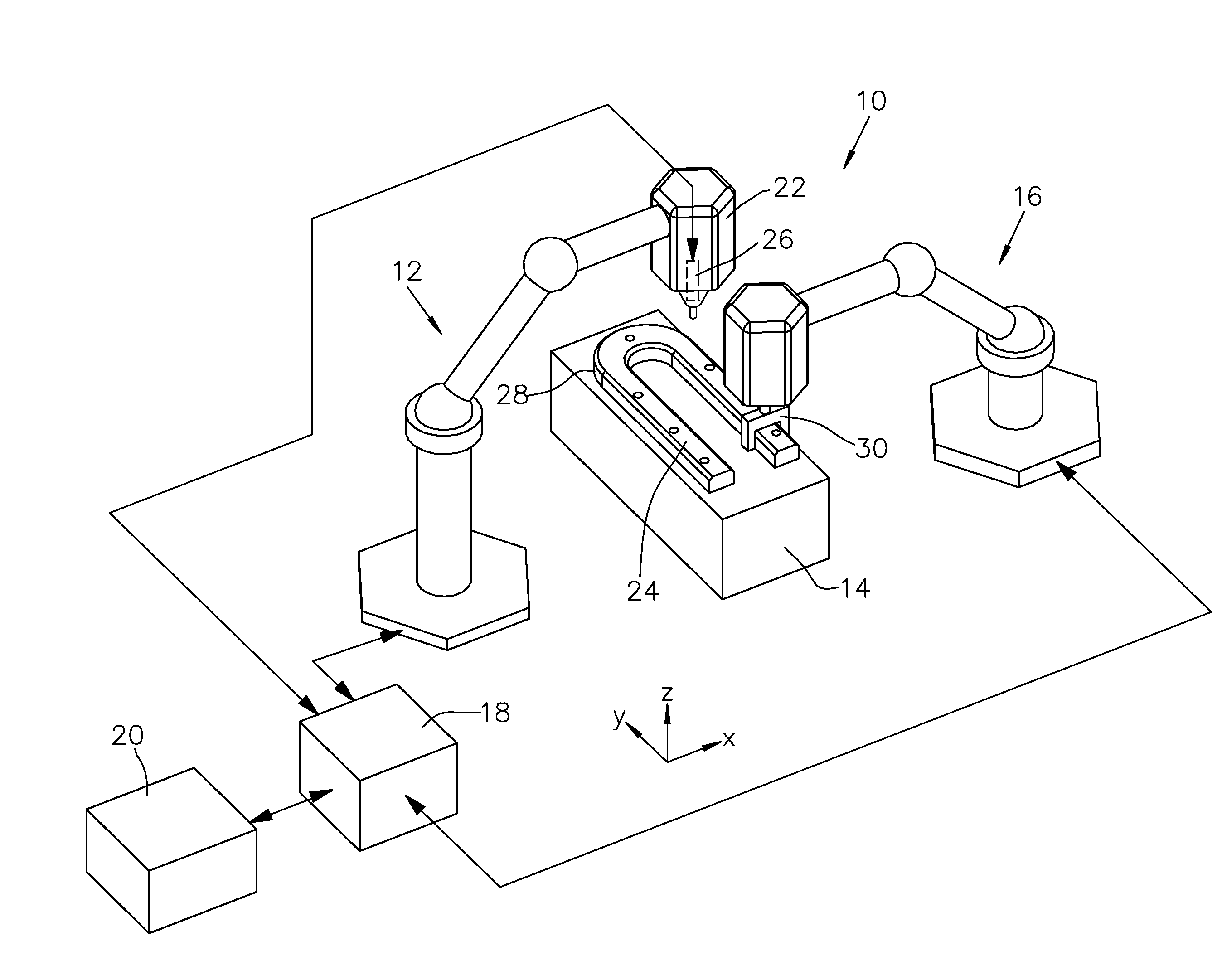
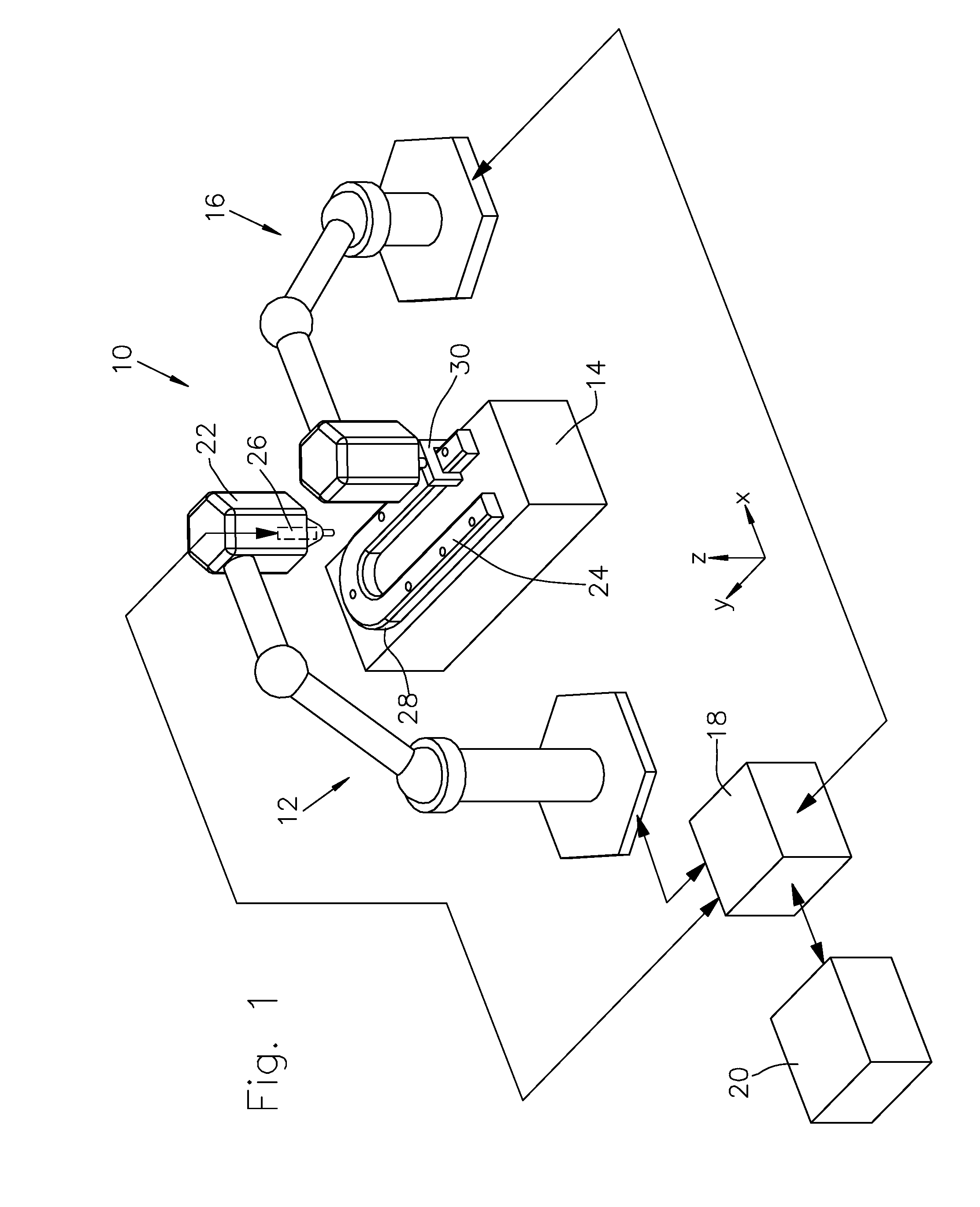
[0017]FIG. 1 shows an electronically controlled laser beam cutting system 10. The system 10 includes a first electronically controlled robot or manipulator 12, a tool table 14, a second electronically controlled robot or manipulator 16, an electronic, preferably programmable, control unit 18, and also a data input and data output system or data read-in and data read-out system 20.

[0018]The first robot 12 is provided with a laser cutting head 22 and is formed in such a way that it can move or position the latter spatially, that is to say in at least three degrees of freedom (x, y, z). The robot 12 is preferably formed in such a way that, with respect to a workpiece 24 positioned on the tool table 14, it can move or position the laser cutting head 22 along the surface of the workpiece 24 with respect to fixed reference points on the workpiece. The robot 12 is activated by means of the electronic control unit 18, the electronic control unit 18 sending control signals to a robot control...


PUM

PropertyMeasurementUnit
Distanceaaaaaaaaaa

Abstract

A laser cutting system and method are provided. The system (10) includes an electronically controllable robot (12) for bringing a laser cutting head (22) to prescribable reference positions with respect to a workpiece (24), a programmable control device (18), provided with a memory, for controlling the robot (12) with respect to reference position coordinates stored in the memory, and a distance correcting device (26) for correcting the distance of the laser cutting head (22) from the workpiece after the laser cutting head (22) has been brought to the reference position defined by the reference position coordinates. To ensure a prescribed quality standard during the laser cutting, certain tolerances on the workpiece (24) must be maintained. In order to avoid additional measuring steps for measuring the workpiece (24), the control unit (18) is formed and programmed so that a comparison of the position coordinates acquired by the control unit (18) after distance correction of the laser cutting head (22) with the reference position coordinates stored in the memory takes place before a laser cutting process is initiated.

Description

FIELD OF THE INVENTION[0001]The present invention relates to a system and a method for the laser cutting of a workpiece.BACKGROUND OF THE INVENTION[0002]It is known to use laser cutting systems to process workpieces, in particular for forming indentations or recesses into the workpiece.[0003]Such a system and an associated method are disclosed, for example, in DE 37 00 829 A1. The latter relates in particular to a system and a method for laser beam work such as cutting, welding and the like, in order for metal cutting operations to be carried out on an assembly line by means of a laser beam. The system has a relatively elaborate process of using sensors to control the position of the laser beam head or the cutting nozzle.[0004]DE 34 45 981 A1 discloses a system and a method for processing workpieces with a laser beam emerging from a laser head, the system having a height sensing device, which is used for regulating or monitoring an in-focus distance of the laser head from the workpi...

Claims


Application Information

Patent Timeline
IPC IPC(8): B23K26/00
CPCB23K26/0876B23K26/046
Inventor MORITZ, MICHAELMETZGER, THOMAS
Owner DEERE & CO
Why Eureka
Try Eureka