Island submount and a method thereof

a sub-mount and island technology, applied in the field of sub-mounts, can solve the problems of re-absorption and weakening the energy of output light at las

Inactive Publication Date: 2009-04-02
IND TECH RES INST
View PDF6 Cites 16 Cited by
  • Summary
  • Abstract
  • Description
  • Claims
  • Application Information

AI Technical Summary

Benefits of technology

[0009]To avoid the absorption of the light from below the light-emitting element to reflect back to the light-emitting element, the present invention provides an island submount which is a substrate having an island structure and a method thereof.

Problems solved by technology

However, the light emerging from below the light-emitting element 11 may still enter the light-emitting element 11 after being reflected by the surface of the submount 13, thus resulting in re-absorption and weakening the energy of the output light at last.

Method used


Image

  • Island submount and a method thereof
  • Island submount and a method thereof
  • Island submount and a method thereof

Examples


first embodiment

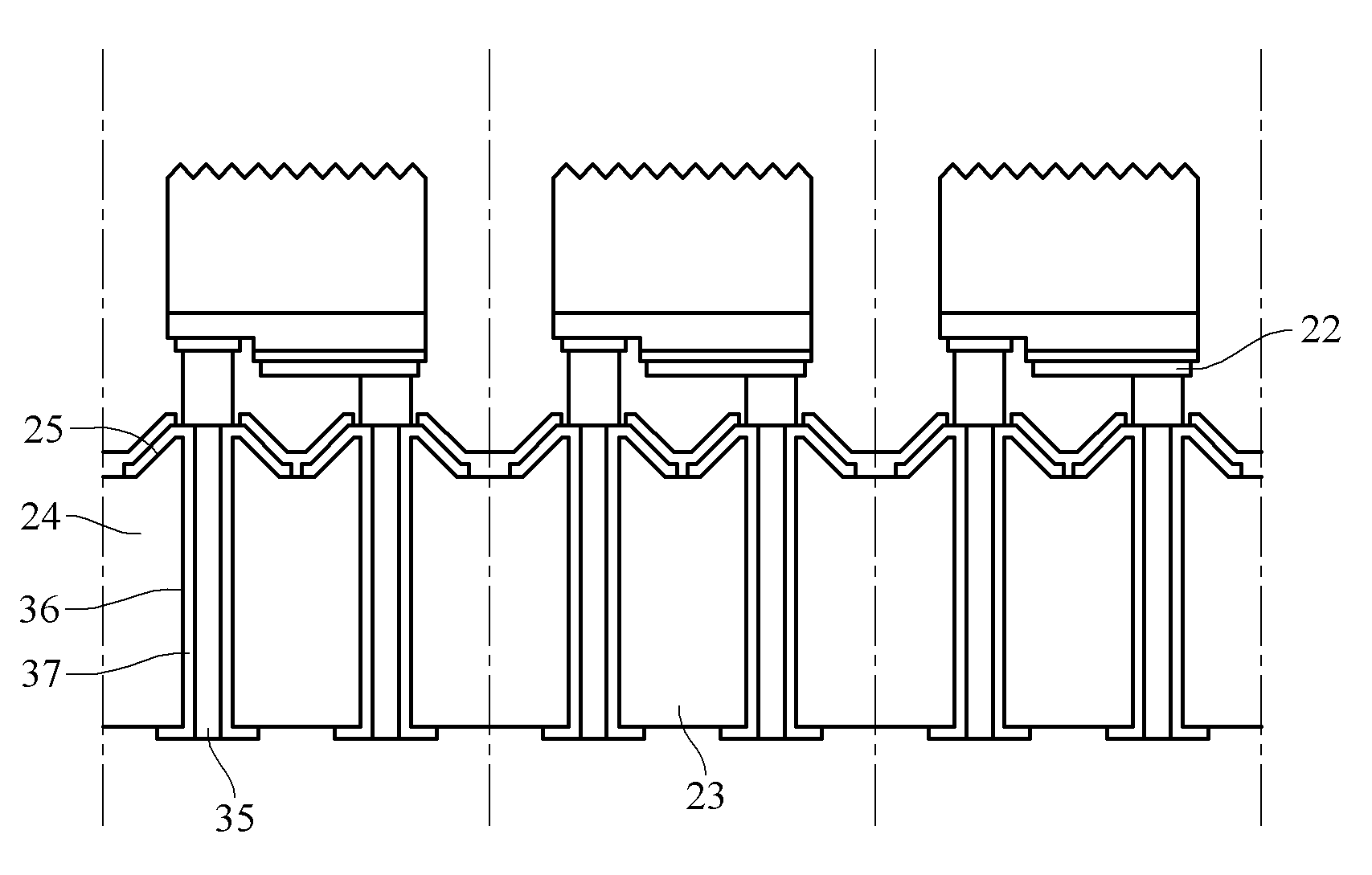
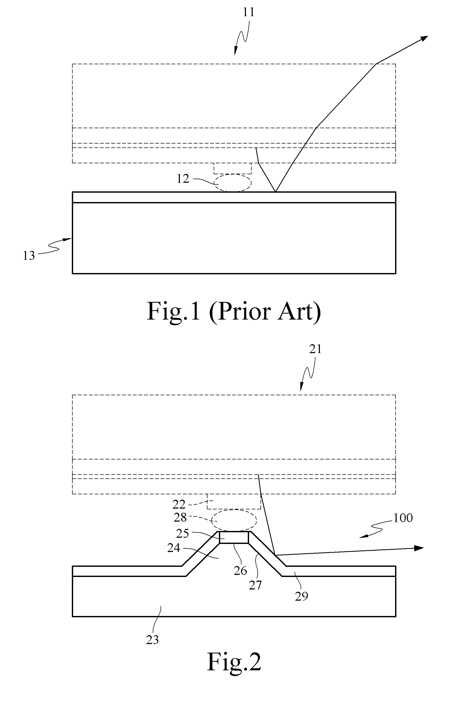
[0039]Referring to FIG. 2, a schematic view of the present invention is shown. An island submount 100 is provided for carrying a light-emitting element 21 having an electrical contact 22. The island submount 100 includes a substrate 23, an island structure 24, and a conductive layer 25.

[0040]The substrate 23 is made of a thermal conductive material, such as semiconductor, ceramic, or metal material.

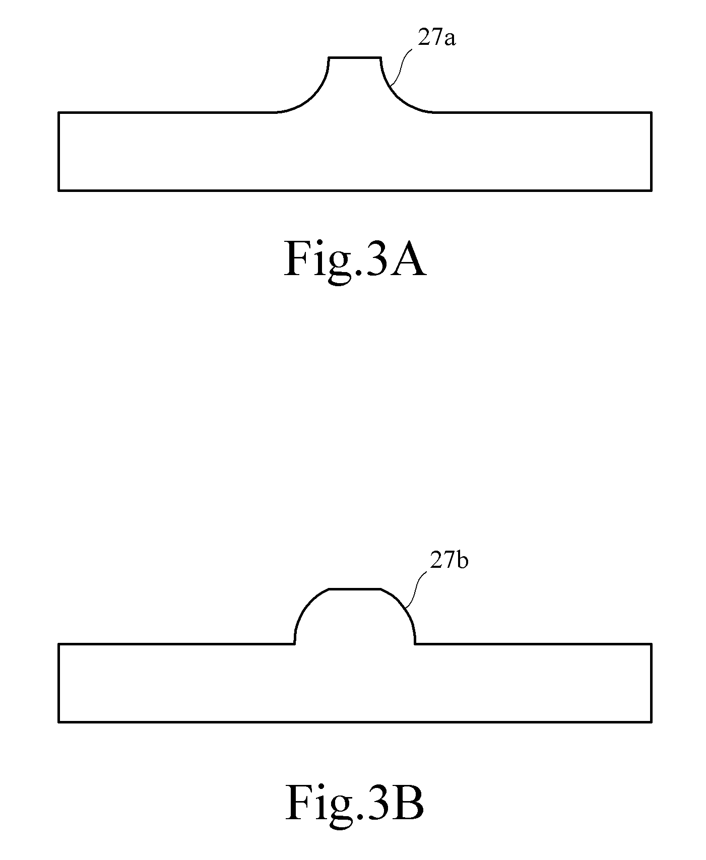
[0041]The island structure 24 is formed on the substrate 23 and corresponding to the electrical contact 22 of the light-emitting element 21. The island structure 24 has a top surface 26 and an inclined surface 27.

[0042]The conductive layer 25 is covered on the top surface 26 of the island structure 24, for electrically connecting to the electrical contact 22 of the light-emitting element 21 corresponding to the island structure 24. The conductive layer 25 is electrically connected to the electrical contact 22 of the light-emitting element 21 through a connection layer 28. The connection l...

third embodiment

[0046]Referring to FIG. 5, a schematic view of the present invention is shown. An island submount 200 is provided for carrying a light-emitting element 121 having two electrical contacts 122a, 122b of opposite electrical properties. The island submount 200 includes a substrate 123, two island structures 124a, 124b, and two conductive layers 125a, 125b.

[0047]The substrate 123 is made of a thermal conductive material, such as semiconductor, ceramic, metal material, glass fiber, or bakelite.

[0048]The two island structures 124a, 124b are formed on the substrate 123. Each of the island structures is corresponding to an electrical contact of the light-emitting element. That is, the two island structures 124a, 124b are respectively corresponding to the two electrical contacts 122a, 122b of opposite electrical properties of the light-emitting element 121. The two island structures 124a, 124b respective have top surfaces 126, 128 and inclined surfaces 127, 129.

[0049]The two conductive layer...

fourth embodiment

[0051]Referring to FIG. 7, a schematic top view of the present invention is shown. The island submount 300 of this embodiment is constituted by a plurality of island submounts 200 arranged in an array.

[0052]Referring to FIG. 8, a schematic view of a fifth embodiment of the present invention is shown. The structure of the island submount of this embodiment has been disclosed in the first embodiment, and the same parts can refer to the above description and will not be described herein again. This embodiment is characterized in that the island submount 100 further includes a transparent protection layer 30 or a light-transmissive protection layer. The transparent protection layer 30 or the light-transmissive protection layer is covered on the reflective layer 29 corresponding to the inclined surface 27, for protecting the reflective layer 29 from being damaged by external forces. The transparent protection layer 30 or the light-transmissive protection layer is made of a transparent or...


PUM


Abstract

An island submount used for carrying at least one light-emitting element having at least one electrical contact. The island submount includes a substrate, at least one island structure having a top surface and an inclined surface, and a conductive layer. The island structure is located on the substrate and corresponds to the electrical contact. The conductive layer is formed on the surface of the island structure and at least covers the top surface, so as to be electrically connected with the electrical contact. The island submount is capable of enhancing the light extraction efficiency of the light-emitting element, and avoids the energy loss due to re-absorption when the light emerging from below the light-emitting element is reflected back to the light-emitting element.

Description

CROSS-REFERENCE TO RELATED APPLICATIONS[0001]This non-provisional application claims priority under 35 U.S.C. §119(a) on Patent Application No(s). 0961364445 filed in Taiwan, R.O.C. on Sep. 28, 2007, the entire contents of which are hereby incorporated by reference.BACKGROUND OF THE INVENTION[0002]1. Field of Invention[0003]The present invention relates to a submount, and more particularly to a submount having an island structure used for carrying a light-emitting element.[0004]2. Related Art[0005]The light-emitting principle of light-emitting diodes (LEDs) is to form a p-n junction with different doping modes. When electrons and holes are combined, the energy is released in the form of light, and the light is substantially a set of infinite multi-point light sources. LEDs are advantageous in high durability, long service life, light weight, and low power consumption. Besides, LEDs do not contain hazardous substances like mercury. Therefore, the illumination market has a high expect...

Claims


Application Information

Patent Timeline
Patent Type & Authority Applications(United States)
IPC IPC(8): H01L21/28F21V7/00H05K3/02F21V21/00H05K3/00H01L33/00H01L33/48
CPCH01L33/486H05K1/0306H05K1/053H05K1/111Y10T29/49155H05K3/4007H05K2201/09045H05K2201/10106H01L2224/16H05K1/113H01L2224/05568H01L2224/05573H01L2924/00014H01L2224/05599
Inventor GUO, YIH-DERTSAY, JENQ-DARLIU, PO-CHUN
Owner IND TECH RES INST
Why Eureka
Try Eureka