Fuel cell, electronic apparatus and camera

a fuel cell and electronic equipment technology, applied in cell components, instruments, television systems, etc., can solve the problems of ineffective use of large electric power consumption of digital cameras, and difficulty in providing sufficient energy to the camera, so as to increase the lamination number or the area of cells, the effect of supplying a large amount of energy and effectively using space in the apparatus body

Inactive Publication Date: 2009-04-02
CANON KK
View PDF6 Cites 20 Cited by
  • Summary
  • Abstract
  • Description
  • Claims
  • Application Information

AI Technical Summary

Benefits of technology

[0013]An object of the present invention is to provide a fuel cell that can use space in the apparatus body effectively and supply a large amount of energy by increasing the lamination number or area of cells, a electronic apparatus and camera with the same.

Problems solved by technology

Therefore, the digital camera consumes a large amount of electric power, and thereby requiring a battery having a sufficient energy supplying ability.
However, it becomes difficult to supply sufficient energy to the camera for driving it by a conventional primary battery or rechargeable battery because of reduction in size and weight of the camera.
In other words, the space in which the fuel cell is arranged cannot be used effectively.

Method used


Image

  • Fuel cell, electronic apparatus and camera
  • Fuel cell, electronic apparatus and camera
  • Fuel cell, electronic apparatus and camera

Examples


embodiment 1

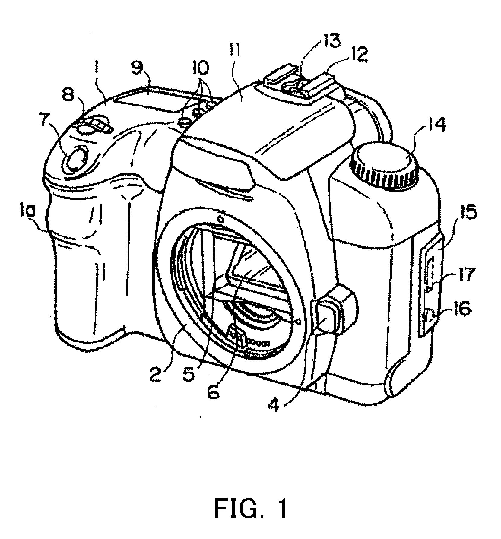
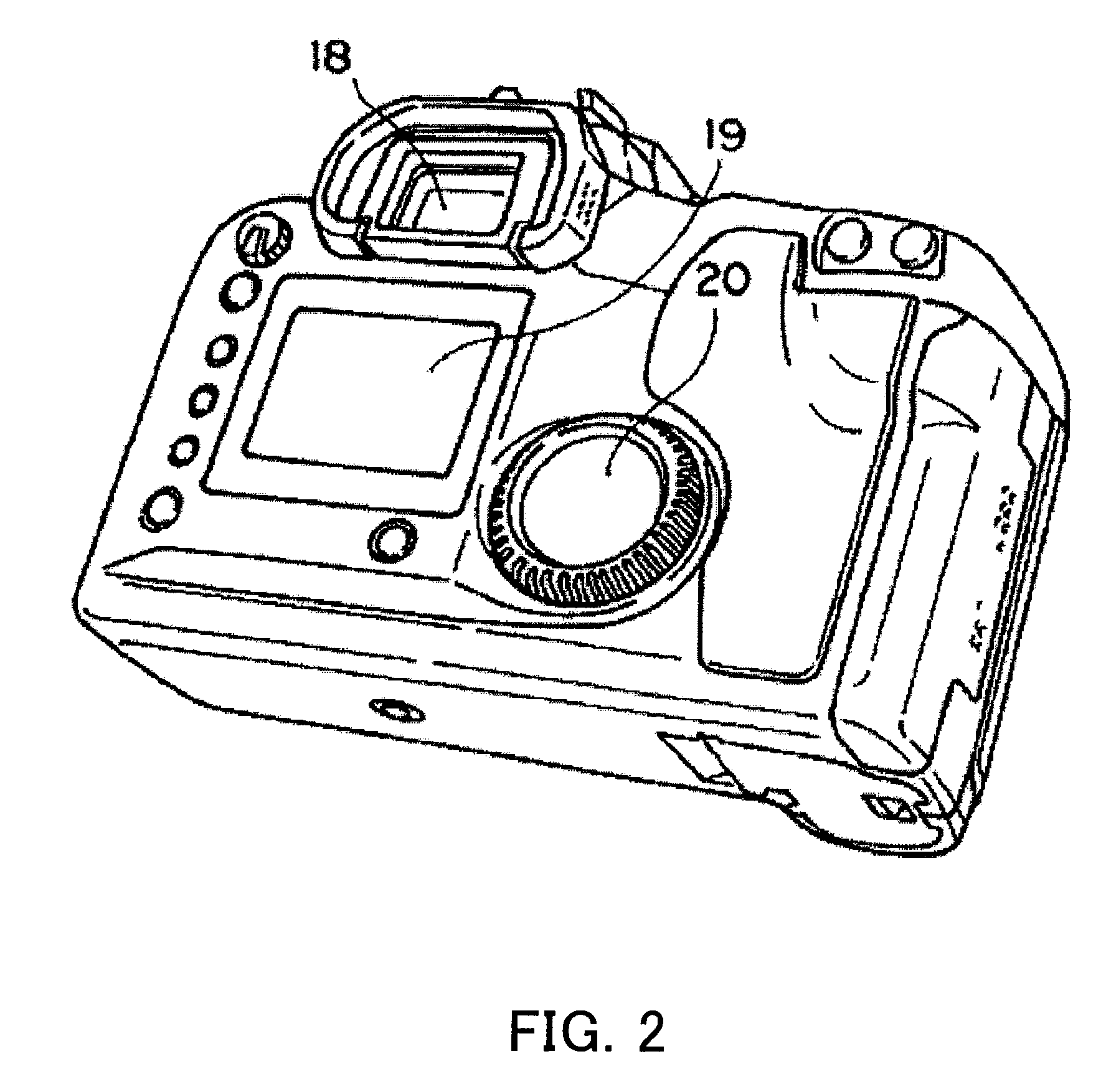
[0038]FIG. 1 is a front perspective view of a camera (electronic apparatus) of Embodiment 1 of the present invention. FIG. 2 is a rear perspective view of the camera of Embodiment 1. FIG. 3 is an observation view of the camera of Embodiment 1. In FIG. 3, a part of the exterior of the camera is omitted so that the fuel cell can be seen to understand the arrangement of a fuel cell easily.

[0039]Each of FIG. 1 and FIG. 2 shows a state in which the camera without a lens apparatus, and FIG. 3 shows the camera with the lens apparatus attached on a mount portion 2 of the camera.

[0040]First, the outline of the camera will be explained using FIG. 1 and FIG. 2. The reference numeral 1 denotes an exterior member forming the exterior of the camera, the exterior member constituting a camera body. In the left area of the exterior member 1 when viewed from the front, a grip portion 1a protruding forward is provided. A user can hold the camera stably by gripping the grip portion 1a at the time of im...

embodiment 2

[0062]Next, a fuel cell of Embodiment 2 of the present invention will be explained using FIG. 4. FIG. 4 is a sectional top view of a camera of Embodiment 2; FIG. 4 shows a section of the neighboring part of a grip portion that is a part of the camera.

[0063]In the grip portion 1a protruding forward from the camera, a cell box 41 that is a power source is housed, the cell box 41 being connected to a fuel tank, not shown in the figure, via a valve. The cell box 41 has a shape following that of the grip portion 1a as Embodiment 1.

[0064]In the cell box 41, a plurality of cells 41a are laminated in the anteroposterior direction of the camera. The cells 41a arranged in the rear portion of the camera have the same length in the direction orthogonal to the lamination direction and the same area. The lengths of the cells 41a in the direction orthogonal to the lamination direction, which are arranged in the front portion of the camera, become smaller continuously or stepwise toward the front. ...

embodiment 3

[0066]Next, a fuel cell of Embodiment 3 of the present invention will be explained using FIG. 5. FIG. 5 is a sectional top view of a camera of Embodiment 3; FIG. 5 shows a section of part where the fuel cell is arranged. The physical structure of each cell is similar to that of Embodiment 1, and the explanation thereof are omitted.

[0067]The mirror box 5 holding the quick-return mirror 6, which was explained in Embodiment 1, is arranged at the substantial center of the camera.

[0068]A focal plane shutter 21 is arranged behind the quick-return mirror 6, the focal plane shutter 21 being held by the mirror box 5.

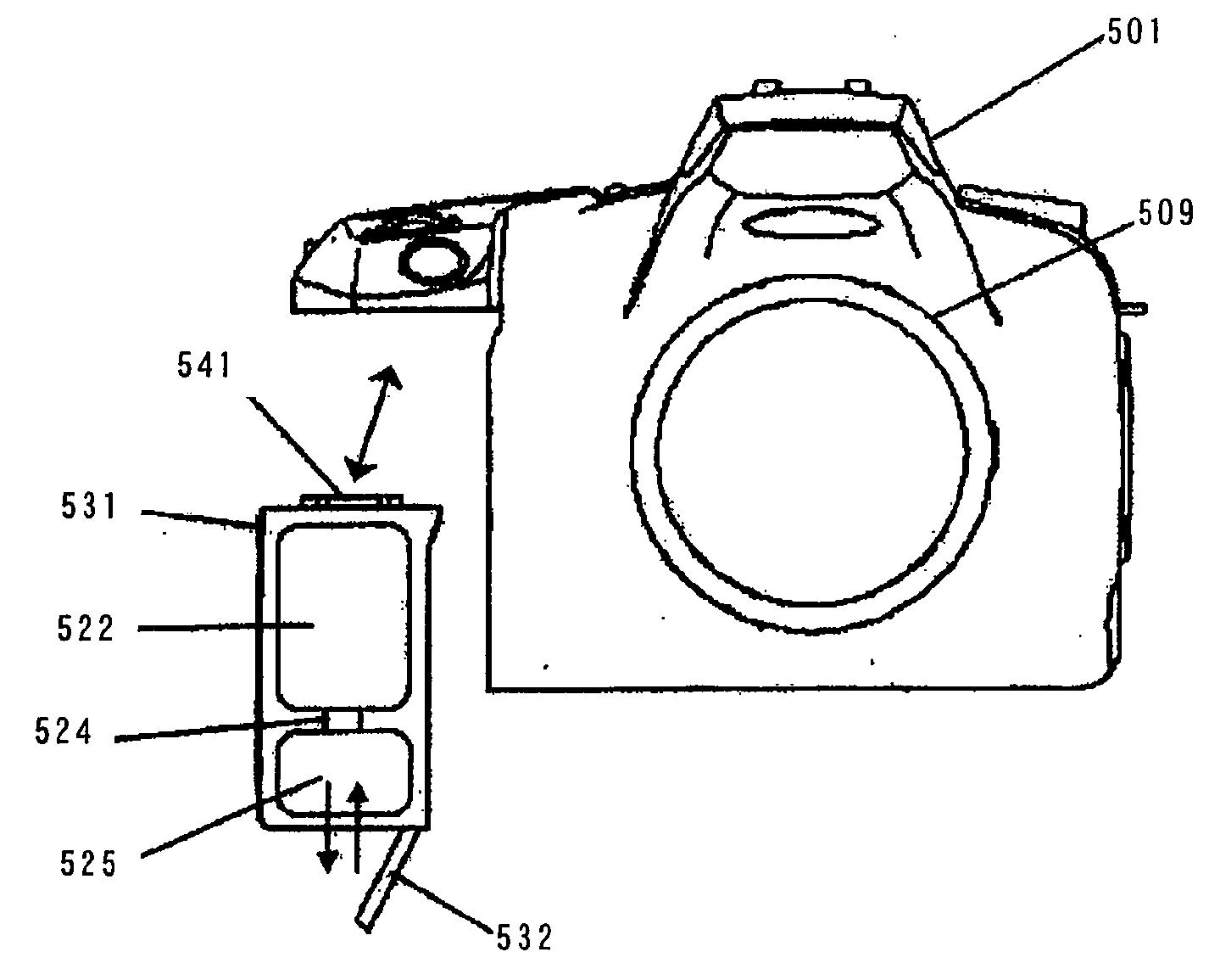
[0069]An image-pickup device 22, such as a CCD sensor and a CMOS sensor, has an image-pickup plane orthogonal to an optical axis L of the image-taking lens 30. An object image formed on the image-pickup plane by the image-taking lens 30 is electrically converted into electric signals by the image-pickup device 22. The electric signals are recorded to recording media, not shown in...


PUM

PropertyMeasurementUnit
angleaaaaaaaaaa
pressureaaaaaaaaaa
pressureaaaaaaaaaa

Abstract

A fuel cell is disclosed, which can use space in an apparatus body effectively. The fuel cell comprises a plurality of cells laminated, and a cell box housing the plurality of cells. The plurality of cells include a cell whose size in a first direction orthogonal to a lamination direction is different from that of another cell. The cell box has a shape corresponding to the size of each cell. Furthermore, an electronic apparatus is disclosed, which comprises an apparatus body including a grip portion having a protruding shape; and a fuel cell that is housed in the grip portion and comprises a cell section in which a plurality of cells are laminated in a protrusion direction of the grip portion or a direction orthogonal to the protrusion direction.

Description

CROSS-REFERENCE TO RELATED APPLICATIONS[0001]This application is a divisional of application Ser. No. 11 / 079,987, filed Mar. 15, 2005, the entire disclosure of which is hereby incorporated by reference.FIELD OF THE INVENTION[0002]The present invention relates to fuel cells, which are used for electric apparatuses such as cameras and supply electric power thereto.BACKGROUND OF THE INVENTION[0003]Digital cameras are known, each of which electrically converts object images formed by an image-taking lens into image signals using a solid image-pickup device such as a CCD sensor, records A / D-converted image signals to recording medium, and displays images on a built-in liquid crystal monitor.[0004]Especially, in a single-lens reflex digital camera including an interchangeable lens, it is required to have a good operationality, high-speed continuous shooting performance, high quality image taking ability and image taking ability for wide luminance range, similar to silver-halide film camer...

Claims


Application Information

Patent Timeline
Patent Type & Authority Applications(United States)
IPC IPC(8): H04N5/225H01M2/02H01M8/04H01M8/06H01M8/24
CPCH01M8/04089H01M8/04208H01M8/065Y02E60/50H01M8/2475H01M2250/30Y02B90/18H01M8/241Y02B90/10
Inventor KIKUCHI, HIROSHITOTORI, YUKIURAKAMI, TOSHIFUMITOKURA, GO
Owner CANON KK
Why Eureka
Try Eureka