Manufacturing method of thin-film magnetic head with dishing suppressed during polishing

a thin-film magnetic head and polishing technology, applied in the field of manufacturing methods of thin-film magnetic heads, can solve the problems of large coarseness and minuteness of the head pattern, difficult to maintain the pasting accuracy of the other parts, and the planarization process of the shield becomes a problem, etc., to achieve stable and higher reliability, and stable and higher reliability. the effect of conta

Inactive Publication Date: 2009-04-02
TDK CORPARATION
View PDF3 Cites 3 Cited by
  • Summary
  • Abstract
  • Description
  • Claims
  • Application Information

AI Technical Summary

Benefits of technology

[0022]According to the thin-film magnetic head provided such dishing prevention portion, a height from the element formation surface of the head substrate of the dishing prevention portion can be adjusted depending on a height of the magnetic layer of the read head portion 21 and the write head portion 22. That is, the dishing prevention portion functions as an adjustment portion of the electrode position. This can make a whole upper surface of the overcoat layer parallel to the element formation surface of the head substrate. As a result, an upper surface (pad) of the electr

Problems solved by technology

In the manufacturing method of the chiplet type, it is difficult to maintain a pasting accuracy during pasting the others parts, but the full span type does not have this difficulty and widely used.
However, in the manufacturing method of the full span type, especially, a dishing to occur in a planarization process of a shield becomes a problem.
In the manufacturing method of the full span type, especially, the degree of the coarseness and minuteness of the head pattern is large, then the dishing becomes the problem.
The place to occur the dishing is usually a place to be formed a electrode pad such as a RLG pad, for example, this causes a defect such that an upper surface of the formed electrode pad tilts toward the element formation surface of the wafer substrate.
Especially, in subsequent process, an magnetoresistive (MR) effect multilayer which is a magneto-sensitive portion is formed on a plurality of lower shields, but if the layer thickness of the lower shield has the distribution, a focus exposure toward a resist la

Method used


Image

  • Manufacturing method of thin-film magnetic head with dishing suppressed during polishing
  • Manufacturing method of thin-film magnetic head with dishing suppressed during polishing
  • Manufacturing method of thin-film magnetic head with dishing suppressed during polishing

Examples


Embodiment Construction

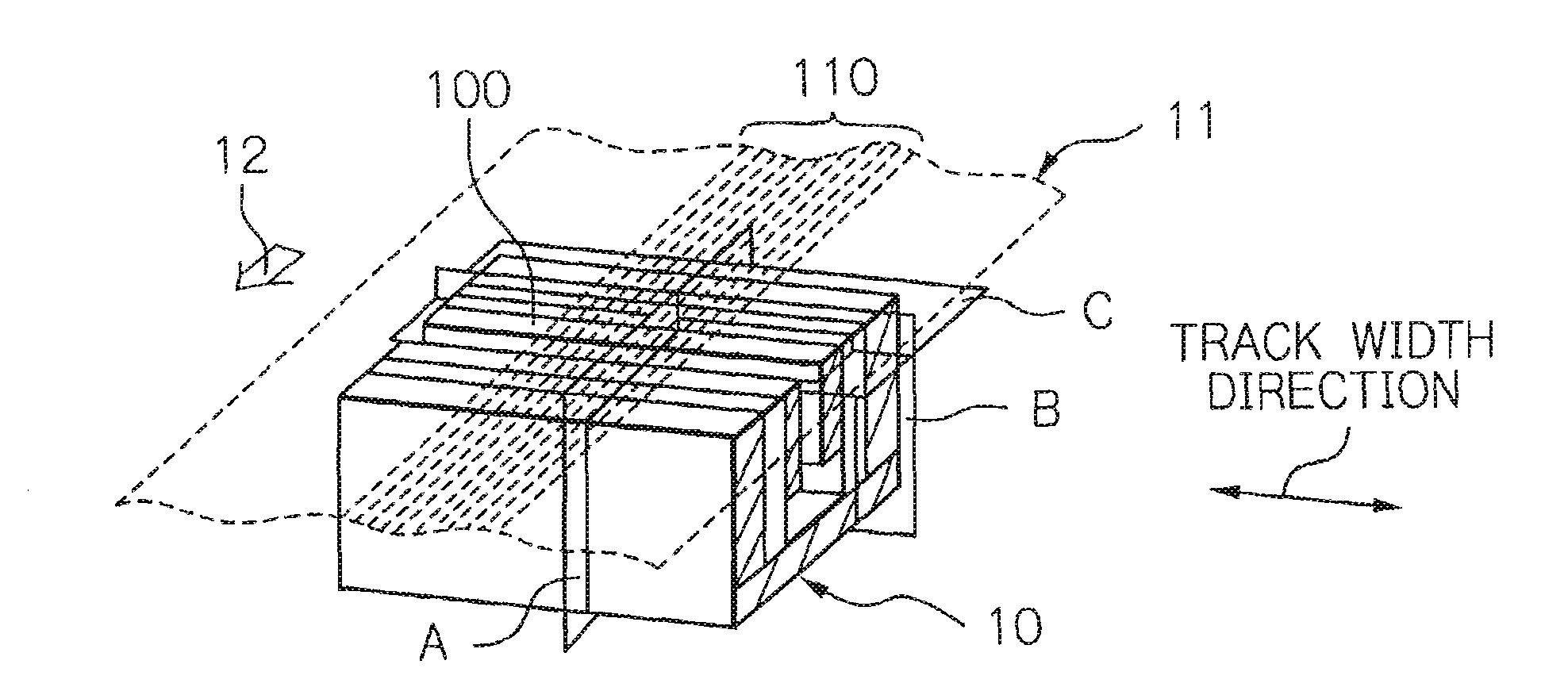
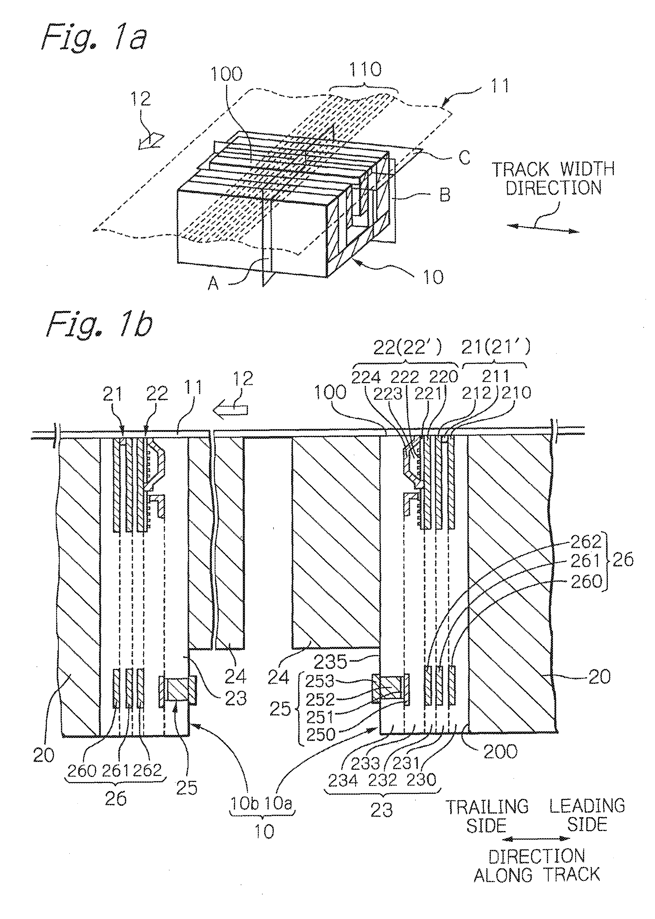
[0034]FIG. 1a shows a perspective view schematically illustrating a configuration of an embodiment of the thin-film magnetic head according to the present invention. Also FIG. 1b shows a cross-sectional view taken along plain A in FIG. 1a, illustrating a main part of the thin-film magnetic head according to the present invention.

[0035]According to FIG. 1a, reference numeral 10 denotes a tape head as a thin-film magnetic head for a magnetic tape, 11 denotes a magnetic tape as a magnetic recording medium with a plurality of tracks 110. The magnetic tape moves to direction of an arrow 12 in recording / reproducing. Further, the tape head 10 performs writing and reading operation of data signals toward the track 110 of the magnetic tape with contacting the moving tape 11 at a medium opposed surface (a sliding surface) 100 that is a head end surface of its own magnetic tape 11 side.

[0036]According to FIG. 1b, the tape head 10 is provided with a leading portion 10a and a trailing portion 10...


PUM


Abstract

A manufacturing method of a thin-film magnetic head with a dishing suppressed in the case of planarizing a magnetic shield which a read head portion has or a magnetic pole which a write head portion has is provided. A manufacturing method of a thin-film magnetic head comprising a read head portion for data reading which has at least two magnetic layers functioning as a magnetic shield and a write head portion for data writing which has two magnetic layers functioning as a magnetic pole is provided, in a process forming at least the lowest magnetic layer in at least the two magnetic layers functioning as the magnetic shield and the two magnetic layers functioning as the magnetic pole in the case of forming a plurality of thin-film magnetic head patterns on an element formation surface of the wafer substrate, which comprises steps of: forming this magnetic layer so as to reach a position which becomes a medium opposed surface at a middle portion to a trick width direction in each thin-film magnetic head pattern, and forming a dishing prevention portion at a position farther than this magnetic layer from the position which becomes the medium opposed surface in both sides or either side along the track width direction of this magnetic layer; forming a nonmagnetic insulating layer so as to cover the magnetic layer and the dishing prevention portion; and planarizing and polishing the magnetic layer, the dishing prevention portion, and the nonmagnetic insulating layer thereafter.

Description

BACKGROUND OF THE INVENTION[0001]1. Field of the Invention[0002]The present invention relates to a manufacturing method of a thin-film magnetic head, in particular, relates to a manufacturing method with a dishing suppressed during a polishing for planarization. Further, the present invention relates to the thin-film magnetic head manufactured by this method.[0003]2. Description of the Related Art[0004]Recently, in a magnetic recording / reproducing apparatus, high capacity of saved data makes remarkable advance by growth of multimedia or Internet so on. This situation is a same as, for example, a magnetic tape apparatus for data backup or data saving, therefore a high recording density and a multi channel corresponding to the high capacity of saved data are strongly demanded.[0005]A thin-film magnetic head is widely used in such magnetic recording / reproducing apparatus, it makes data writing to a magnetic recording medium and data reading from the magnetic recording medium. In the th...

Claims


Application Information

Patent Timeline
IPC IPC(8): G11B5/33
CPCG11B5/00826G11B5/3173G11B5/3169G11B5/3163
Inventor HIRAKI, TETSUYAYARI, SEIJIUNO, YASUFUMISATO, HIDEAKIMASUDA, TAKAHIDEKOBAYASHI, KAZUHIRO
Owner TDK CORPARATION
Why Eureka
Try Eureka