Spring device and timepiece

a technology of a spring device and a timepiece, which is applied in the direction of clock driving mechanisms, instruments, and horology, can solve the problems of insufficient torque, insufficient power consumption of the mainspring, and difficult design and manufacturing of such products, and achieve the effect of increasing the duration time of the mainspring and reducing siz

Active Publication Date: 2009-04-02
SEIKO EPSON CORP
View PDF4 Cites 7 Cited by
  • Summary
  • Abstract
  • Description
  • Claims
  • Application Information

AI Technical Summary

Benefits of technology

[0007]The spring device and timepiece according to the present invention enable further

Problems solved by technology

Both such designs and manufacturing such products are difficult.
With the configuration taught in Japanese Patent 3582383, however, output power from the mainspring is consumed by winding the spring when the mainspring unwinds and output drops because the barrel wheel and ratchet wheel are connected by a wheel train, and there may not be enough torque to drive the timepiece.
This can be resolved by increasing the maximum output torque of the spring, but increasing th

Method used


Image

  • Spring device and timepiece
  • Spring device and timepiece
  • Spring device and timepiece

Examples


embodiment 2

[0181]FIG. 25 is a plan view of part of a timepiece according to a second embodiment of the invention. The timepiece according to the first embodiment of the invention is an electronically controlled mechanical timepiece that has a crystal oscillation circuit. The timepiece according to this embodiment of the invention is a mechanical timepiece that mechanically produces the time standard by means of a regulator that operates in conjunction with the drive wheel train.

[0182]The movement of the timepiece according to this embodiment of the invention includes a barrel 1, the wheels of a drive wheel train for driving hands not shown, an escapement including an escape wheel and pallet fork, and a regulator with a balance. The mechanical timepiece of this embodiment has the same duration time display mechanism (power reserve mechanism), torque limiter mechanism, movement stopping mechanism, and torque return mechanism described in the first embodiment above.

[0183]The duration time indicat...

embodiment 3

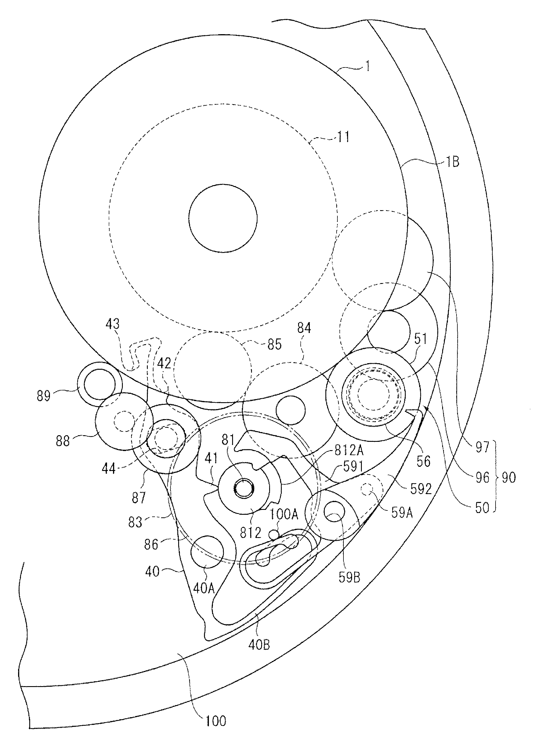
[0187]FIG. 26 is a partial plan view of a mechanical timepiece according to a third embodiment of the invention. This embodiment does not have the torque limiter mechanism and movement stopping mechanism described above. The configuration of the mechanical timepiece according to this embodiment of the invention is otherwise the same as the configuration of the mechanical timepiece according to the second embodiment described above.

[0188]This embodiment of the invention does not have the torque limiter lever 40 (FIG. 2), the second working part 812B and the third working part 812C of the sun cam 812′ associated with the torque limiter mechanism and movement stopping mechanism. The shaft of the first torque return transfer wheel 96′ is also different from the first embodiment, and is rendered using a single part.

[0189]Because the electronically controlled mechanical timepiece described above requires a high precision movement, the rotor may turn too quickly if the mainspring is overwo...


PUM


Abstract

A spring device having an inside-end wheel that moves in conjunction with the inside end of a mainspring; an outside-end wheel that moves in conjunction with the outside end of the mainspring; a torque return unit that transfers part of the output torque of the mainspring from one to the other of the inside-end wheel and outside-end wheel; a duration time indicating unit that operates in conjunction with both the inside-end wheel and outside-end wheel and indicates the number of winds in the mainspring; and a torque transfer clutch unit that disengages torque transfer between the inside-end wheel and outside-end wheel by means of the torque return unit when the mainspring unwinds and the duration time indicating unit indicates a predetermined reference number of winds.

Description

BACKGROUND[0001]1. Field of Invention[0002]The present invention relates to a spring device and to a timepiece having this drive device.[0003]2. Description of Related Art[0004]Mechanical timepieces and electronically controlled mechanical timepieces use a mainspring as the drive power source. Assuming the same number of winds, the mechanical energy / volume ratio of a mainspring increases as the maximum output torque increases. The duration time of the mainspring can therefore be increased by either using a spring with greater torque or reducing the torque required to drive the wheel train, but these methods create the need for design changes such as increasing the speed-increasing ratio from the barrel to the second wheel or making the wheel diameters and wheel modules smaller. Both such designs and manufacturing such products are difficult.[0005]As described in Japanese Patent 3582383, we developed a mainspring torque output device that connects the barrel wheel and ratchet wheel u...

Claims


Application Information

Patent Timeline
IPC IPC(8): G04B1/10
CPCG04B9/02G04B1/10
Inventor TAKAHASHI, OSAMUHIROSE, NOBUYUKIMAEJIMA, MASAAKIMOTEKI, MASATOSHI
Owner SEIKO EPSON CORP
Why Eureka
Try Eureka