Optical fiber cables

a technology of optical fiber cables and fiber mechanical structures, applied in the direction of optics, instruments, fibre mechanical structures, etc., can solve the problems of difficult connectorization, excessive universal design, and high cost, and achieve the effect of convenient connectorization, low cost and compact siz

Inactive Publication Date: 2009-04-02
FURAKAWA ELECTRIC NORTH AMERICA INC
View PDF4 Cites 44 Cited by
  • Summary
  • Abstract
  • Description
  • Claims
  • Application Information

AI Technical Summary

Benefits of technology

[0012]New designs for FTTP drop cable that offer compact size and

Problems solved by technology

However, this method of termination requires expensive capital equipment and highly skilled craft in order to produce robust splices at the customer premises.
However, as applied to many current applications the universal designs are excessively large, and are difficult to connectorize.
However, for some important drop installations, typically indoor applications, this cable is either overdesigned or underdesigned in the following particulars.
These cables are rigid and stiff, and difficult to bend or handle.
They have a preferred bending axis due to the racetrack shape, making bending difficult in directions other than the preferred axis.The 300 lb. tensile requirement leads to a large cable footprint, typically about 4×8 mm.The non-circular cross-section of the cable, as well as the preferred bendi

Method used


Image

  • Optical fiber cables
  • Optical fiber cables

Examples


Embodiment Construction

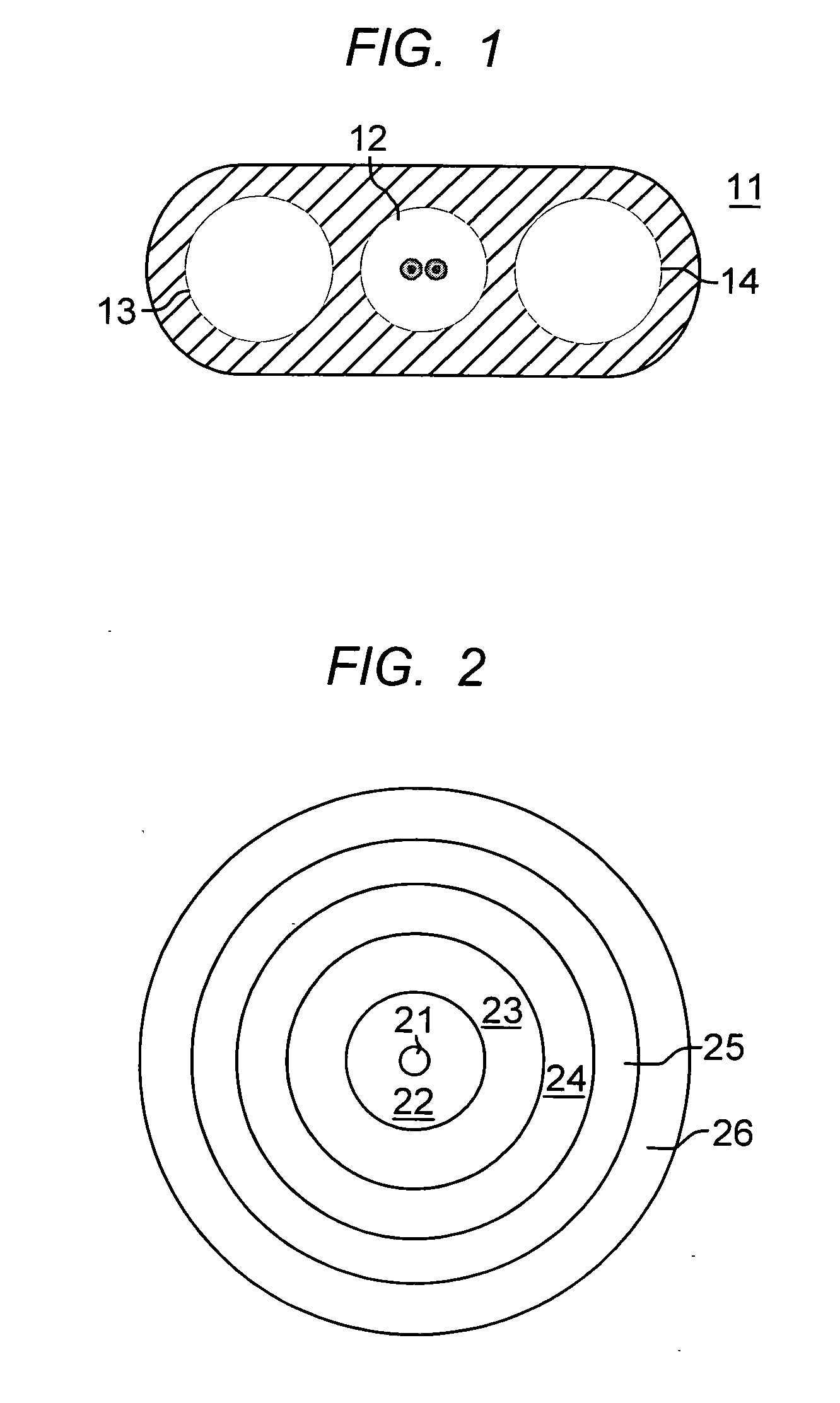
[0016]The dual-jacketed, all dielectric, self-supporting cable of the invention is shown in FIG. 2. The design comprises an optical fiber subunit with optical fiber 21, surrounded by a tightly buffered layer 22. The tight buffered optical fiber subunit is a 250 micron fiber buffered up to a diameter of 0.9 mm (buffer layer thickness 650 microns). Other tight buffered optical fiber subunit diameters, typically 0.4 mm to 1.2 mm may be used. This allows termination with piece parts of standard optical connectors. The tight buffer layer completely surrounds and encases the optical fiber, meaning that the buffer layer contacts the optical fiber coating of the optical fiber. The tight buffer layer is a polymer, for example, PVC, nylon, polyolefins, polyester thermoplastic elastomers, fluoropolymers, UV-curable acrylates, or a combination of these materials. While the preferred optical fiber subunit contains a single optical fiber, equivalent cable designs may have optical fiber subunits w...


PUM


Abstract

An optical fiber cable suitable for drop cable applications has a dual jacket, dual reinforcement layers, a round cross section, and a tight buffered construction. The optical fiber cable is a compact unitary coupled fiber assembly that has a small profile, and is light in weight, while still sufficiently robust for many indoor/outdoor drop cable installations. The small profile and round construction make the cable easy to connectorize.

Description

RELATED APPLICATION[0001]This application claims priority from U.S. Provisional Application No. 60 / 975,830 filed Sep. 28, 2007.FIELD OF THE INVENTION[0002]This invention relates to optical fiber cables specially adapted for drop line applications.BACKGROUND OF THE INVENTION[0003]Fiber-to-the-premises (FTTP) from local telephone and cable service providers is rapidly being implemented. This service requires a broadband optical fiber distribution network comprising local optical fiber distribution cables installed in neighborhoods and along city streets. The local distribution cable is a large fiber count (multi-fiber) cable. Single fiber or few fiber cables are used for the “drop” line from the street to the premises. In many cases, aerial drop lines are used, and these have special requirements. In other cases, cables are buried in earth or installed in conduit. These installations have different requirements.[0004]In all cases, the ‘drop’ cable must be terminated at the subscriber ...

Claims


Application Information

Patent Timeline
IPC IPC(8): G02B6/36G02B6/44
CPCG02B6/4432
Inventor BRADLEY, KELVIN B.WEIMANN, PETER A.
Owner FURAKAWA ELECTRIC NORTH AMERICA INC
Why Eureka
Try Eureka