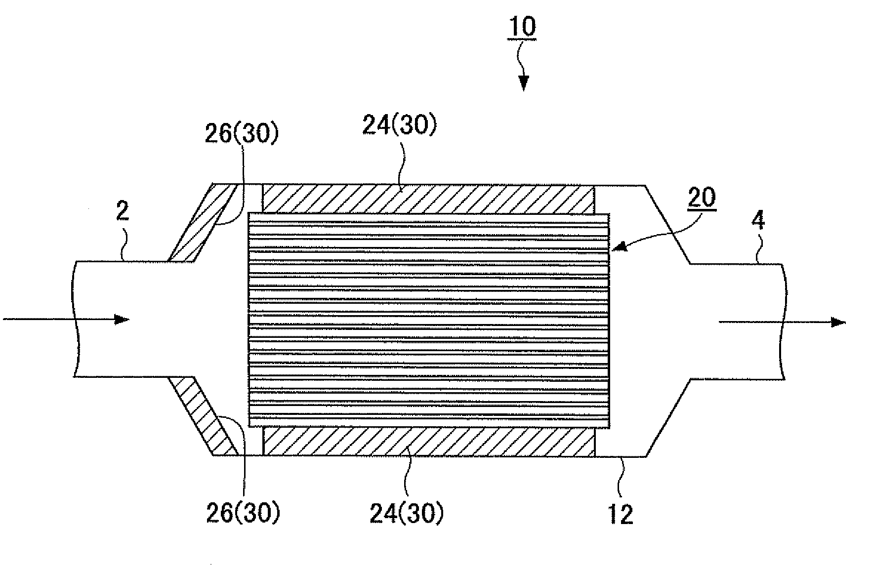
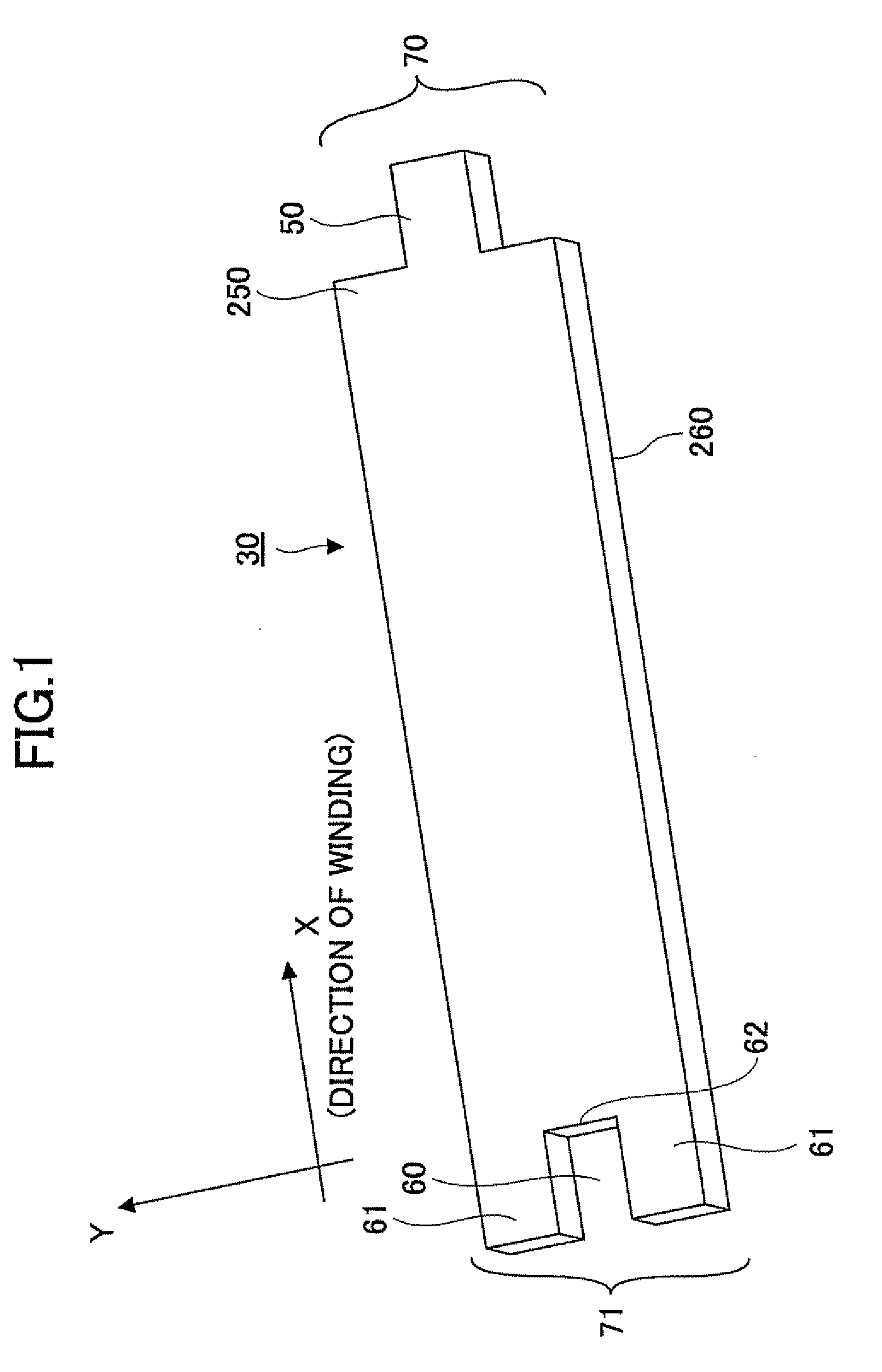
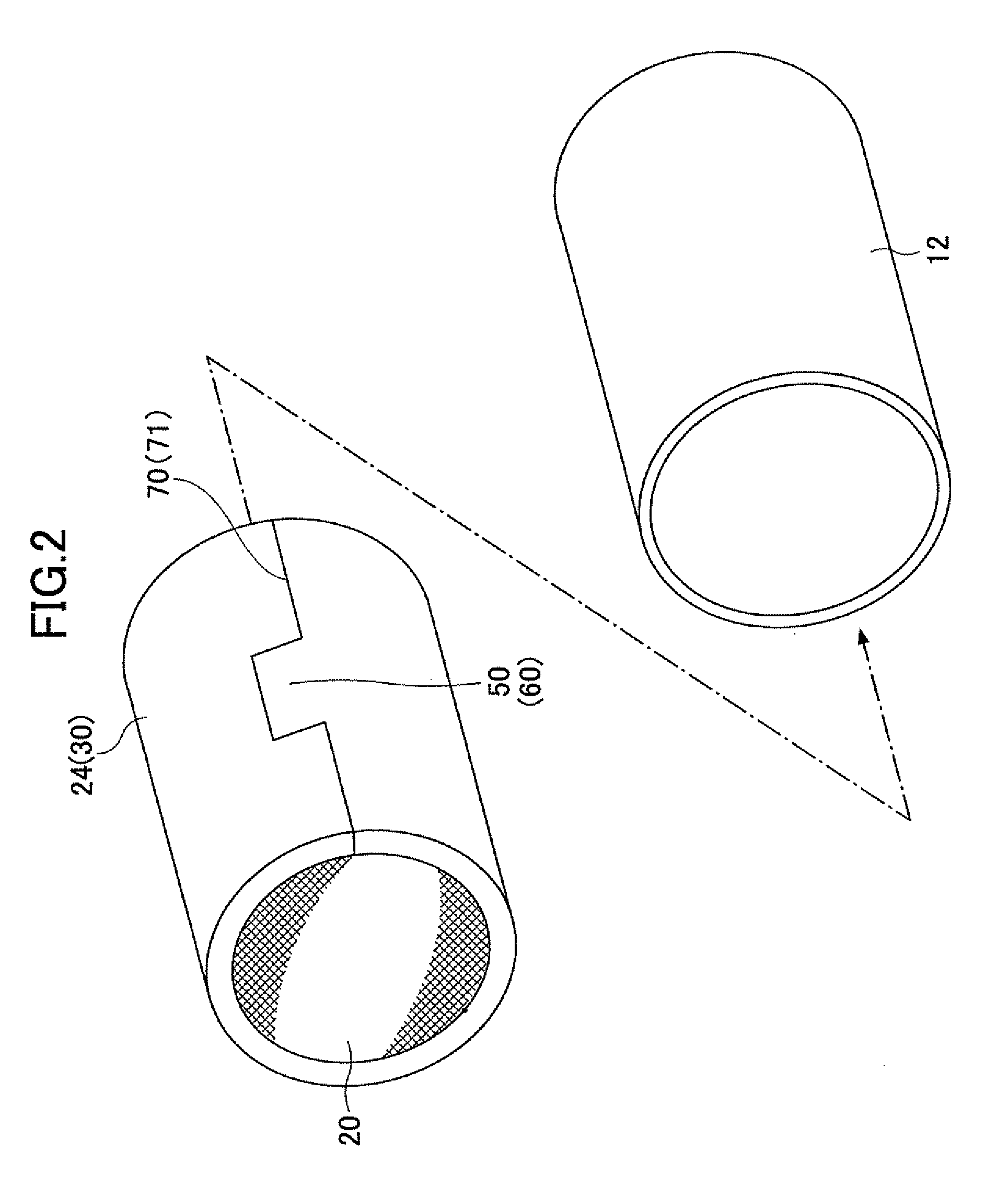
Mat material, exhaust gas treating apparatus, and muffler

a technology of exhaust gas treatment and mufflers, which is applied in the direction of machines/engines, filtration separation, separation processes, etc., can solve the problems of major pollution and serious affecting the global environment, and achieve the effect of improving handleability

Active Publication Date: 2009-04-02
IBIDEN CO LTD
View PDF11 Cites 24 Cited by
  • Summary
  • Abstract
  • Description
  • Claims
  • Application Information

AI Technical Summary

Benefits of technology

[0021]Thus, in accordance with an embodiment of the invention, a mat material having an appropriate interlaminar strength and improved handleability is provided. In another embodiment, an exhaust gas treating appara

Problems solved by technology

Particularly, various substances contained in diesel engine exhaust gases ar

Method used


Image

  • Mat material, exhaust gas treating apparatus, and muffler
  • Mat material, exhaust gas treating apparatus, and muffler
  • Mat material, exhaust gas treating apparatus, and muffler

Examples


example 1

[0092]A mat material was manufactured by the following procedure.

[0093]A silica sol was added to a basic aluminum chloride aqueous solution with an aluminum content of 70 g / l and Al / C=11.8 (atomic ratio) to achieve an alumina-based fiber composition of Al2O3:SiO2=72:28, thereby forming an alumina-based fiber precursor.

[0094]Then, an organic polymer such as polyvinyl alcohol was added to the alumina-based fiber precursor. The solution was further condensed to obtain a spinning solution, with which fiber spinning was performed by a blowing method. Thereafter, the alumina-based fiber precursor was folded and laminated to obtain an alumina-based fiber laminate sheet.

[0095]The laminate sheet was then subjected to a needling process which involved a pair of needle boards, each having a set of 50 needles per 100 cm2. These needle boards were disposed on either side of the laminate sheet, and moved up and down from either side of the laminate sheet substantially along the thickness directio...

example 2

[0098]A mat material according to Example 2 was manufactured by the same method as the foregoing Example 1. In Example 2, the penetration depth of the needle from each surface was set to be 9.5 mm. The basis weight of the mat material was 2000 g / cm2 and the density was 0.16 g / cm3. The thickness of the completed mat material was 12.7 mm, and the penetration depth of the needle trace was 9.5 mm for both the first and the second surfaces. Thus, the mat material of Example 2 belonged to Type III.

example 3

[0099]A mat material according to Example 3 was manufactured by the same method as the foregoing Example 1. In Example 3, the penetration depth of the needle on each surface was set to be 13.1 mm. The basis weight of the mat material was 2600 g / cm2, and the density was 0.15 g / cm3. The thickness of the completed mat material was 17.4 mm, and the penetration depth of the needle trace was 13.1 mm for both the first and the second surfaces. Thus, the mat material of Example 3 belonged to Type III.


PUM

PropertyMeasurementUnit
Thicknessaaaaaaaaaa
Weightaaaaaaaaaa
Thicknessaaaaaaaaaa

Abstract

A mat material includes inorganic fibers, a first surface, and a second surface opposite to the first surface. The mat material has plural needle traces formed by performing a needling treatment. The needle traces extend from the first surface toward the second surface and from the second surface toward the first surface. There is no depth in the mat material that the needle traces do not reach. There is substantially no protrusion of a bundle of the inorganic fibers at a position on the second surface that lies on a line extending from each of the needle traces extending from the first surface. There is substantially no protrusion of a bundle of the inorganic fibers at a position on the first surface that lies on a line extending from each of the needle traces extending from the second surface.

Description

CROSS-REFERENCE TO RELATED APPLICATIONS[0001]The present application claims priority under 35 U.S.C. §119 to Japanese Priority Application No. 2007-255888 filed Sep. 28, 2007, the entire contents of which are hereby incorporated by reference.BACKGROUND OF THE INVENTION[0002]1. Field of the Invention[0003]The present invention relates to mat materials, exhaust gas treating apparatuses, and mufflers.[0004]2. Discussion of the Background[0005]The number of automobiles has drastically increased since the turn of the century, and the amount of exhaust gas emissions from the internal combustion engines of automobiles shows no sign of slowing. Particularly, various substances contained in diesel engine exhaust gases are a major cause of pollution and seriously affecting the global environment.[0006]Under such circumstances, various exhaust gas treating apparatuses have been proposed and put to practical use. A typical exhaust gas treating apparatus comprises an exhaust gas treating member ...

Claims


Application Information

Patent Timeline
IPC IPC(8): B01D53/86B01D46/00B32B3/24F01N1/24F01N3/28
CPCC04B26/00Y10T428/24273C04B2111/00793C04B2111/0081D04H1/465D04H1/48D04H13/005F01N1/10F01N3/0211F01N2310/02F01N2470/02C04B28/00Y02T10/20C04B14/38D04H1/4209Y02T10/12B01D53/86F01N3/28
Inventor OKABE, TAKAHIKO
Owner IBIDEN CO LTD
Why Eureka
Try Eureka