Ultrasonic endoscope

a technology of ultrasonic endoscope and endoscope, which is applied in the field of ultrasonic endoscope, can solve the problems of difficult application of jp-a-9-140706 to ultrasonic endoscope, temperature rise in use of ultrasonic endoscope, etc., and achieve the effect of suppressing the temperature rise of ultrasonic endoscop

Inactive Publication Date: 2009-04-02
FUJIFILM CORP
View PDF6 Cites 16 Cited by
  • Summary
  • Abstract
  • Description
  • Claims
  • Application Information

AI Technical Summary

Benefits of technology

[0014]According to the present invention, the heat generated in the ultrasonic transducer part transfers to the heat radiating member provided on the outer surface of the exterior member via the heat conducting member, and released to the outside from the heat radiating member. Thus, since the heat radiating member is provided on the outer surface of the exterior member, the temperature rise of the ultrasonic endoscope can be suppressed without increase in diameter.

Problems solved by technology

In this regard, not the entire energy of the drive signals is converted into acoustic energy but a significant proportion of the energy becomes heat, and there has been a problem that the temperature rises in use of the ultrasonic endoscope.
Accordingly, it is difficult to apply the technology of JP-A-9-140706 to an ultrasonic endoscope.
However, the outer diameter of the ultrasonic probe needs to be smaller in the case where the ultrasonic probe is inserted into a human body, and it is difficult to apply the technology of JP-P2006-204552A to an ultrasonic endoscope to be inserted into a human body.
However, in an ultrasonic endoscope, the signal cable has a small sectional area, and, if the signal cable is used for heat dissipation, no sufficient heat dissipation effect is obtained due to the small sectional area.

Method used


Image

  • Ultrasonic endoscope
  • Ultrasonic endoscope
  • Ultrasonic endoscope

Examples


Embodiment Construction

[0023]Hereinafter, embodiments of the present invention will be explained in detail with reference to the drawings. The same reference numbers will be assigned to the same component elements and the description thereof will be omitted.

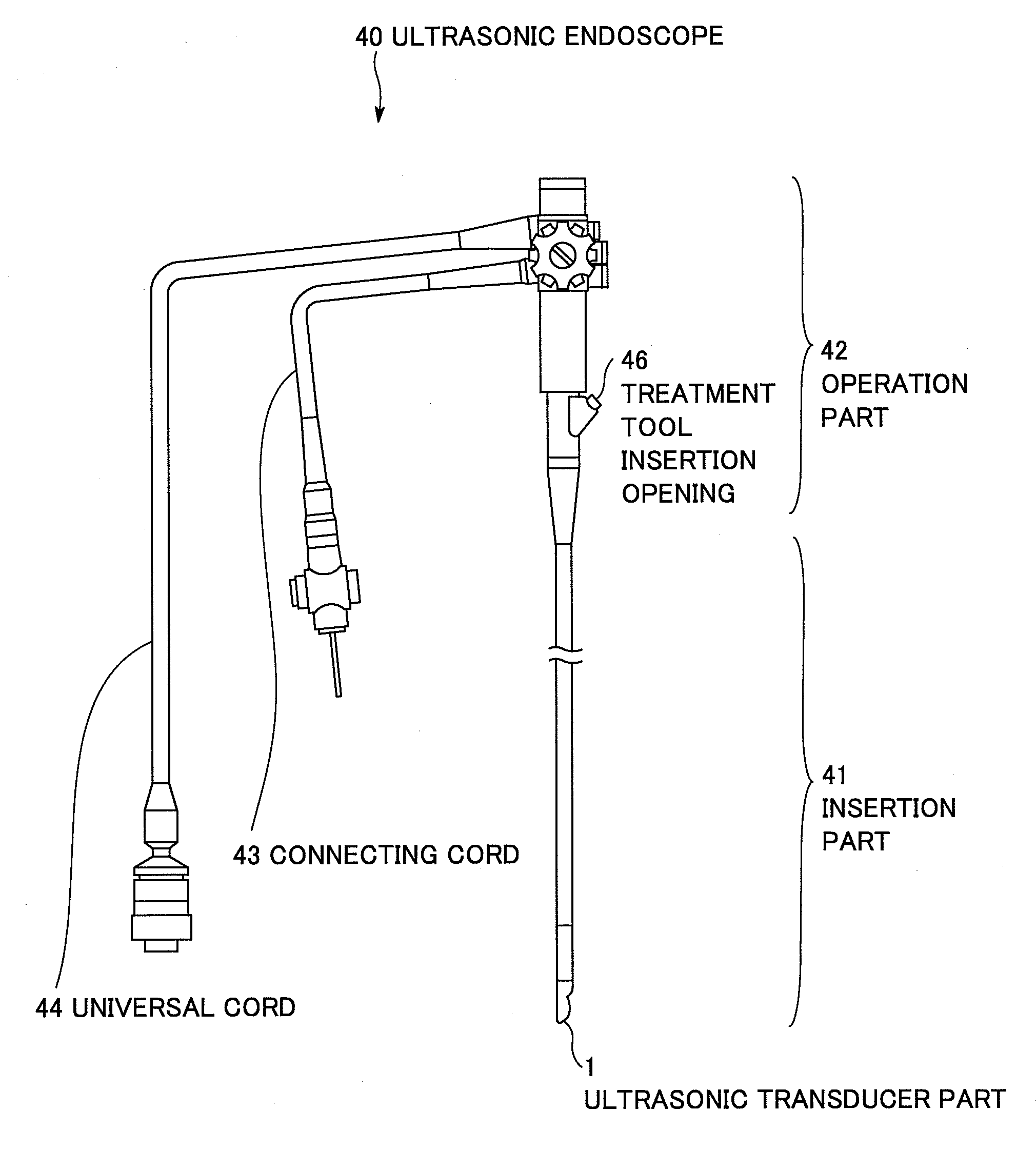
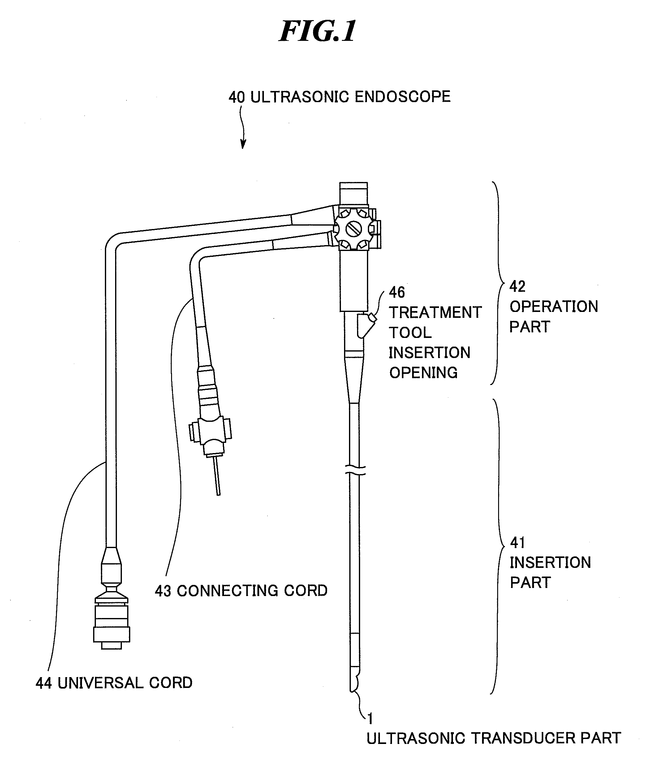
[0024]FIG. 1 is a schematic diagram showing an appearance of an ultrasonic endoscope according to the respective embodiments of the present invention. As shown in FIG. 1, an ultrasonic endoscope 40 includes an insertion part 41, an operation part 42, a connecting cord 43, and a universal cord 44. The insertion part 41 includes an elongated tube formed of a member having flexibility for insertion into the body (e.g., into the bronchial tube) of an object to be inspected, and an ultrasonic transducer part 1 at the leading end thereof.

[0025]The operation part 42 is provided at the base end of the insertion part 41 and connected to an ultrasonic endoscopic apparatus main body (not shown) via the connecting cord 43 and the universal cord 44. A treatment too...


PUM


Abstract

An ultrasonic endoscope capable of suppressing temperature rise of an insertion part without increase in diameter. The ultrasonic endoscope includes: an ultrasonic transducer part having plural ultrasonic transducers; an exterior member for holding the ultrasonic transducer part; an opening formed in the exterior member; a heat conducting member arranged inside of the exterior member and connected to the ultrasonic transducer part; and a heat radiating member provided on an outer surface of the exterior member and connected to the heat conducting member via the opening. For example, a part of the heat radiating member is located within the opening and the part is connected to the heat conducting member. The heat radiating member is electrically insulated from the ultrasonic transducer part.

Description

BACKGROUND OF THE INVENTION[0001]1. Field of the Invention[0002]The present invention relates to an ultrasonic endoscope to be used for body cavity examination of upper digestive organs, bronchial tube, and so on.[0003]2. Description of a Related Art[0004]In medical fields, various imaging technologies have been developed in order to observe the interior of an object to be inspected and make diagnoses. Among them, especially, ultrasonic imaging for acquiring interior information of the object by transmitting and receiving ultrasonic waves enables image observation in real time and provides no exposure to radiation unlike other medical image technologies such as X-ray photography or RI (radio isotope) scintillation camera. Accordingly, ultrasonic imaging is utilized as an imaging technology at a high level of safety in a wide range of departments including not only the fetal diagnosis in the obstetrics, but also gynecology, circulatory system, digestive system, etc.[0005]The ultrason...

Claims


Application Information

Patent Timeline
Patent Type & Authority Applications(United States)
IPC IPC(8): A61B8/14
CPCA61B8/12A61B8/445A61B8/546A61B8/4488
Inventor NAGANO, KAZUHIKOHYUGA, HIROAKI
Owner FUJIFILM CORP
Why Eureka
Try Eureka