
Fuel Injection Strategy For Gasoline Direct Injection Engine During High Speed/Load Operation

Inactive Publication Date: 2009-04-02
FORD GLOBAL TECH LLC
View PDF13 Cites 31 Cited by
  • Summary
  • Abstract
  • Description
  • Claims
  • Application Information

AI Technical Summary

Benefits of technology

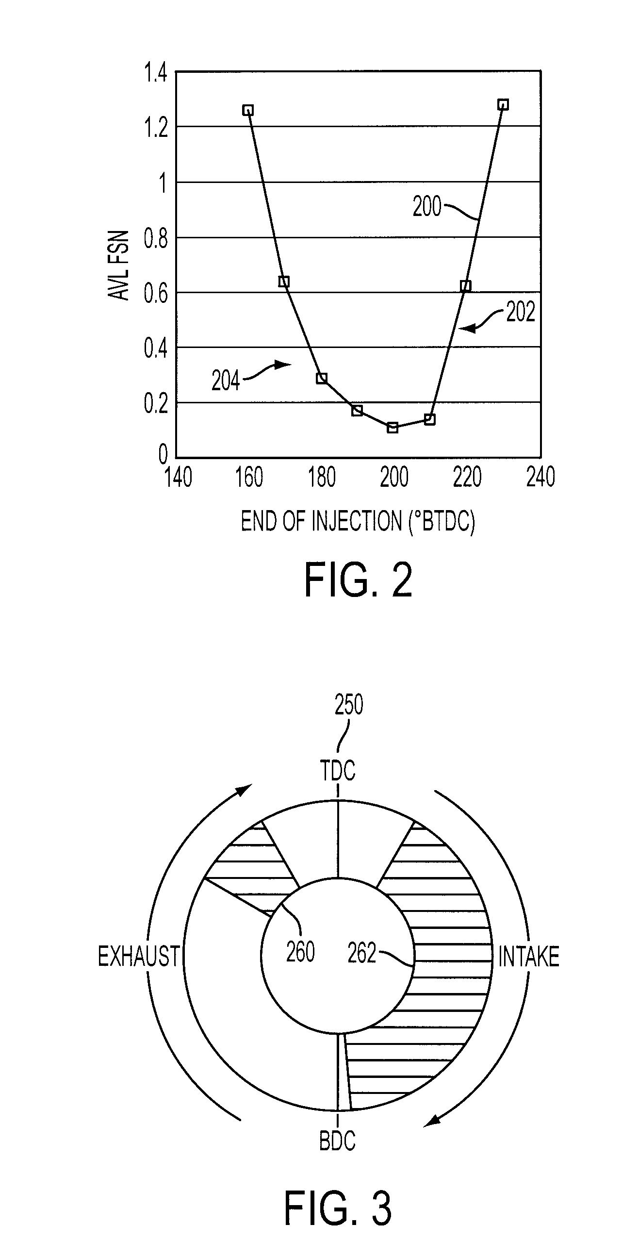
[0008]A system and method for controlling operation of a multiple cylinder direct injection internal combustion engine include injecting a fraction of total fuel injected per engine cycle directly into the combustion chamber during the exhaust stroke at high engine speeds and loads to reduce the effect of intake airflow on the injection spray and improve fuel-air mixture homogeneity.
[0010]The present disclosure includes embodiments having various advantages. For example, the systems and methods of the present disclosure provide increased torque at high engine speeds and loads using a single, low-pressure fuel pump. Embodiments of the present disclosure provide fuel-air mixing homogeneity at high engine speeds and loads resulting in reduced soot. Separation between a first fuel injection and subsequent fuel injection(s) according to the present disclosure increases mixing time and may reduce piston wetting to reduce smoke. Embodiments of the present disclosure facilitate elimination of an auxiliary high-pressure fuel pump reducing cost and complexity of the engine.

Problems solved by technology

More recently, as disclosed in U.S. Pat. No. 6,712,037 for example, gasoline direct injection engines have been developed that rely solely on a low-pressure fuel pump, which provides advantages in terms of lower cost and complexity, but may have reduced cold start performance and reduced maximum torque output at higher engine speeds / loads.
While this approach may be suitable for many applications, it affects operation across the entire operating range and requires increased complexity in the cylinder head to form the deflectors, which may also impact the cost of the system.

Method used


Image

  • Fuel Injection Strategy For Gasoline Direct Injection Engine During High Speed/Load Operation
  • Fuel Injection Strategy For Gasoline Direct Injection Engine During High Speed/Load Operation
  • Fuel Injection Strategy For Gasoline Direct Injection Engine During High Speed/Load Operation

Examples


Embodiment Construction

)

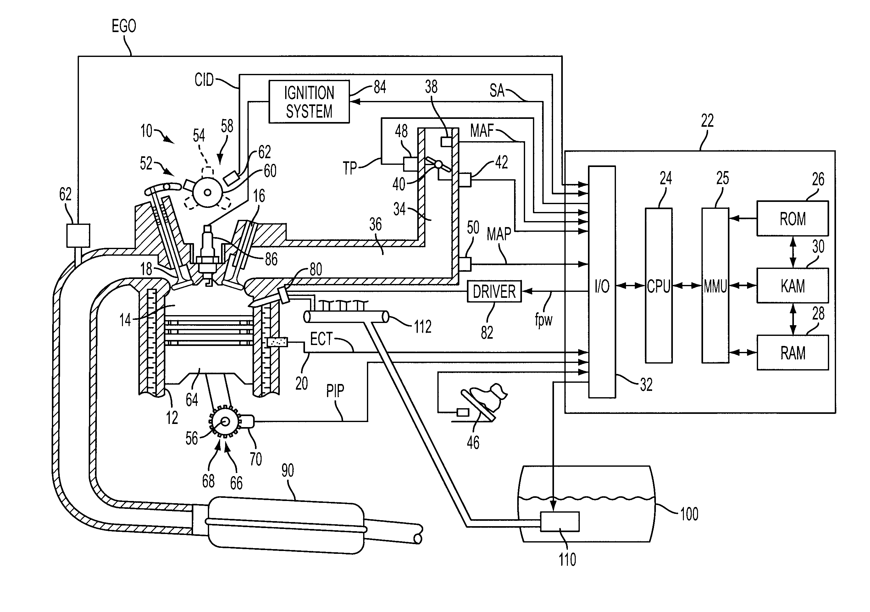
[0021]As those of ordinary skill in the art will understand, various features of the embodiments illustrated and described with reference to any one of the Figures may be combined with features illustrated in one or more other Figures to produce alternative embodiments that are not explicitly illustrated or described. The combinations of features illustrated provide representative embodiments for typical applications. However, various combinations and modifications of the features consistent with the teachings of the present disclosure may be desired for particular applications or implementations. The representative embodiments used in the illustrations relate generally to a four-stroke, multi-cylinder, internal combustion engine with direct or in-cylinder injection. Those of ordinary skill in the art may recognize similar applications or implementations with other engine / vehicle technologies.

[0022]System 10 includes an internal combustion engine having a plurality of cylinders, re...


PUM


Abstract

A system and method for controlling operation of a multiple cylinder direct injection internal combustion engine include injecting fuel directly into the combustion chamber during the exhaust stroke at high engine speeds and loads to reduce the effect of intake airflow on the injection spray and improve fuel-air mixture homogeneity.

Description

BACKGROUND[0001]1. Technical Field[0002]The present disclosure relates to a system and method for fuel injection in a gasoline direct injection engine during high speed / load operation.[0003]2. Background Art[0004]Direct-injection spark-ignition (DISI) internal combustion engines have been developed to reduce fuel consumption and feedgas emissions of gasoline engines. DISI engines may operate in a stratified charge mode with layers or strata of richer air / fuel ratio near the spark plug and progressively leaner layers below under certain operating conditions, such as low to medium loads and engine speeds and during starting, for example. At higher engine loads and speeds, a stoichiometric or slightly rich homogeneous charge is provided where the air-fuel mixture of the charge is generally well-mixed and homogeneous throughout the combustion chamber.[0005]DISI engines have traditionally used a low-pressure fuel pump in combination with an auxiliary or high-pressure fuel pump to produce...

Claims


Application Information

Patent Timeline
IPC IPC(8): F02D41/30
CPCF02D41/401Y02T10/44F02D2041/389F02D41/402Y02T10/40
Inventor YI, JIANWEN JAMESWOOLDRIDGE, STEVEN TODDDAVIS, GEORGE CARVER
Owner FORD GLOBAL TECH LLC
Learn More