
Memory control apparatus, memory control method, and computer program

Active Publication Date: 2009-04-02
SONY CORP
View PDF19 Cites 12 Cited by
  • Summary
  • Abstract
  • Description
  • Claims
  • Application Information

AI Technical Summary

Benefits of technology

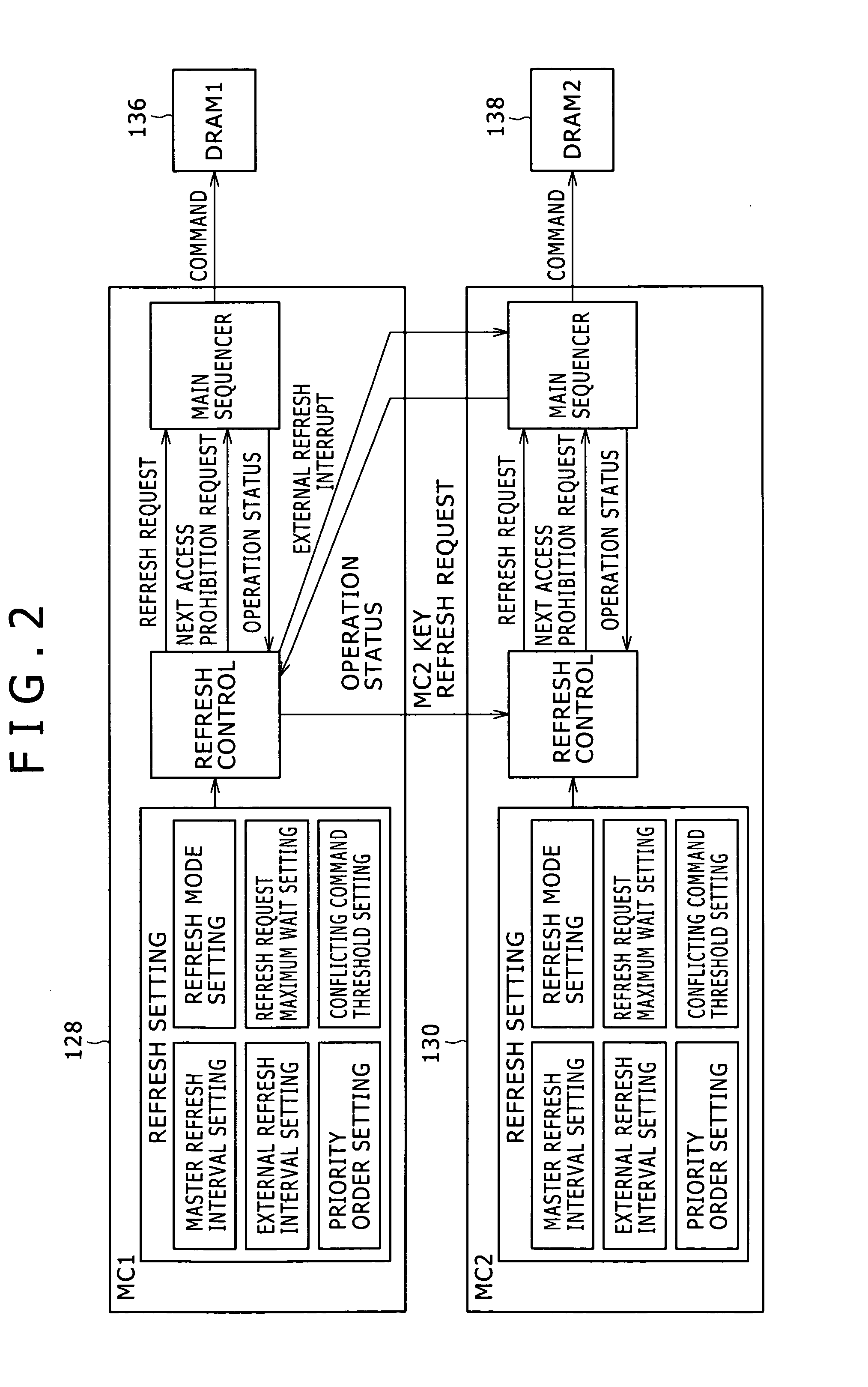
[0011]The present invention addresses the above-identified, and other problems associated with methods and apparatuses in related art, and provides a memory control apparatus, a memory control method, and a computer program which allow arbitrary setting of the timing with which the refresh operations are performed and are capable of avoiding not only the conflict of the refresh operations but also a conflict of commands for operations that consume high power, such as write / read operations, in order to prevent an increase in peak current.
[0030]As described above, the present invention provides the memory control apparatuses, the memory control methods, and the computer programs which allow the timing with which the refresh operations are performed to be set arbitrarily so as to avoid the conflict of not only the refresh operations but also the write / read operations, which consume high power, so that an increase in peak current can be prevented.

Problems solved by technology

In such types of DRAMs, a conflict of read operations results in a higher peak current than a peak current caused by the conflict of refresh operations.
A method as disclosed in Patent Document 1 has a problem in that an optimum number of refresh operations cannot be performed when the DRAMs differ in capacity.

Method used


Image

  • Memory control apparatus, memory control method, and computer program
  • Memory control apparatus, memory control method, and computer program
  • Memory control apparatus, memory control method, and computer program

Examples


first embodiment

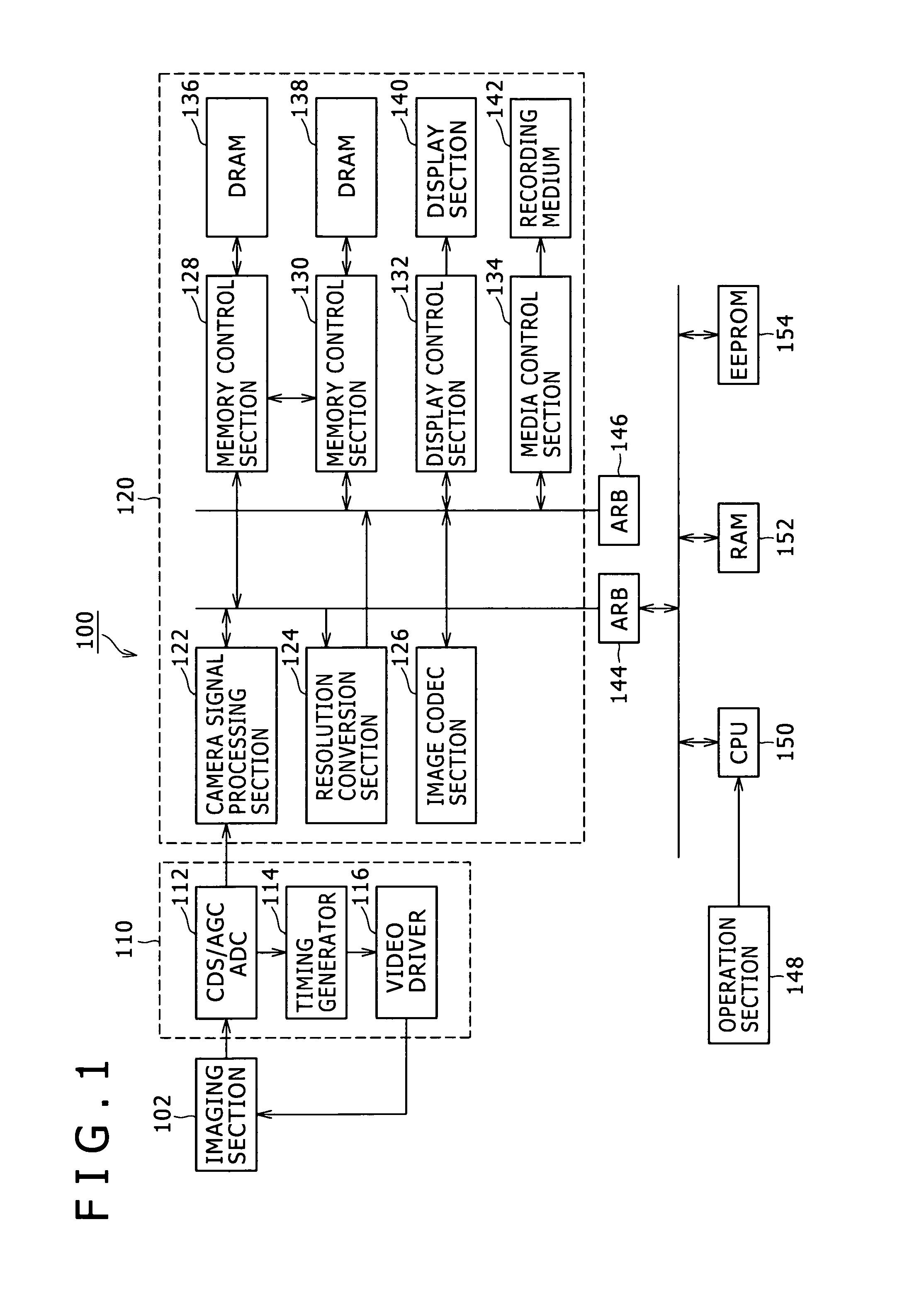
[0042]First, a digital still camera including a memory control apparatus according to a first embodiment of the present invention will be described below.

[0043]FIG. 1 is a block diagram illustrating the structure of the digital still camera 100 according to the first embodiment of the present invention. The structure of the digital still camera 100 according to the first embodiment of the present invention will now be described in detail below with reference to FIG. 1.

[0044]As shown in FIG. 1, the digital still camera 100 according to the first embodiment of the present invention includes an imaging section 102, an image preprocessing section 110, an image processing section 120, a first arbitration section (ARB) 144, a second arbitration section 146, an operation section 148, a central processing unit (CPU) 150, a random-access memory (RAM) 152, and an EEPROM 154.

[0045]The imaging section 102 converts a light from a subject into an electrical signal. Although not shown, the imaging...

second embodiment

[0107]In the first embodiment of the present invention, one DRAM is connected to each of the plurality of memory control sections. In a second embodiment of the present invention, a plurality of DRAMs are connected to one memory control section.

[0108]FIG. 8 is a diagram for explaining the structure of a memory control section 228 according to the second embodiment of the present invention. The structure of the memory control section 228 according to the second embodiment of the present invention will now be described below with reference to FIG. 8.

[0109]The memory control section 228 controls DRAMs 236 and 238. As shown in FIG. 8, the memory control section 228 according to the second embodiment of the present invention includes a refresh setting section 262, a refresh control section 264, and a main sequencer 266. In FIG. 8, the DRAMs 236 and 238 are denoted as DRAM1 and DRAM2, respectively.

[0110]Similar to the refresh setting section 162 according to the first embodiment of the pr...


PUM


Abstract

Disclosed herein is a memory control apparatus including a plurality of memory control sections, each of which has connected thereto one or more memories that require periodic refresh and is configured to perform data write, data read, and refresh operations on the one or more memories. The memory control sections issue, to each of the one or more memories, refresh commands at optimum intervals and with arbitrary timing such that commands that consume high power do not conflict with each other.

Description

CROSS REFERENCES TO RELATED APPLICATIONS[0001]The present invention contains subject matter related to Japanese Patent Application JP 2007-255154, filed in the Japan Patent Office on Sep. 28, 2007, the entire contents of which being incorporated herein by reference.BACKGROUND OF THE INVENTION[0002]1. Field of the Invention[0003]The present invention relates to a memory control apparatus, a memory control method, and a computer program. In particular, the present invention relates to a memory control apparatus, a memory control method, and a computer program for controlling a plurality of memories that require periodic refresh.[0004]2. Description of the Related Art[0005]In electronic devices such as digital cameras or camcorders, dynamic random access memories (DRAMs) are widely used as memory elements for storing data. Types of the DRAMs include double data rate (DDR), DDR2, and low power double data rate (LPDDR).[0006]An increasing number of electronic devices equipped with the DR...

Claims


Application Information

Patent Timeline
IPC IPC(8): G06F12/00
CPCG06F13/1636G11C11/406Y02B60/1228G11C2211/4061G11C11/40611Y02D10/00
Inventor KOGANEZAWA, TOMOHIRO
Owner SONY CORP
Learn More