Shrink tube encapsulated magnet wire for electrical submersible motors

a technology of magnet wire and submersible motor, which is applied in the direction of positive displacement liquid engine, piston pump, plastic/resin/waxes insulator, etc., can solve the problems of wires abraded against one another, electrical short, and typical heat generation of three-phase induction motors, so as to reduce hot spots

Inactive Publication Date: 2009-04-09
BAKER HUGHES INC
View PDF16 Cites 40 Cited by
  • Summary
  • Abstract
  • Description
  • Claims
  • Application Information

AI Technical Summary

Benefits of technology

[0012]The result is that the wires are effectively bound together in a manner that allows oil to move freely in the open space surrounding the wire bundles inside the lamination ...

Problems solved by technology

Electric motor windings tend to vibrate, which can cause the wires to abrade against one another.
If the dielectric coating of the wires is rubbed off, then an electrical short will result.
Three phase induction type moto...

Method used


Image

  • Shrink tube encapsulated magnet wire for electrical submersible motors
  • Shrink tube encapsulated magnet wire for electrical submersible motors
  • Shrink tube encapsulated magnet wire for electrical submersible motors

Examples


Embodiment Construction

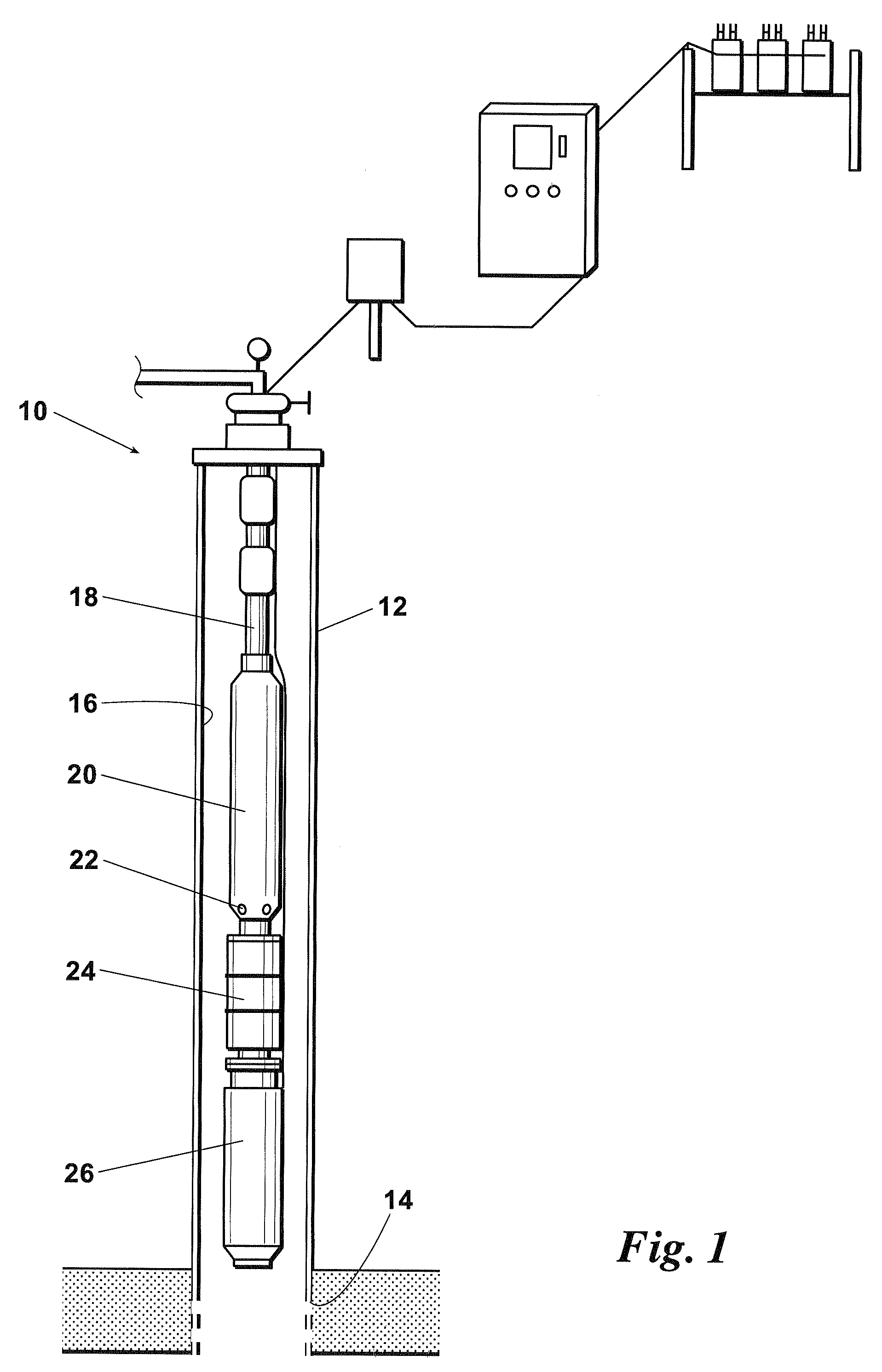
[0016]Referring first to FIG. 1, shown is a well 10 wherein casing 12 surrounds a well bore. Perforations 14 are made in the casing to allow an influx of well fluids. An electrical submersible pump assembly 16 is lowered into well 10 on tubing 18. Electrical submersible pump assembly 16 includes pump 20 having pump intakes 22 for drawing in well fluids. A seal section 24 separates pump 20 from motor 26. Well fluids are pumped to the surface by pump 20 through tubing 18.

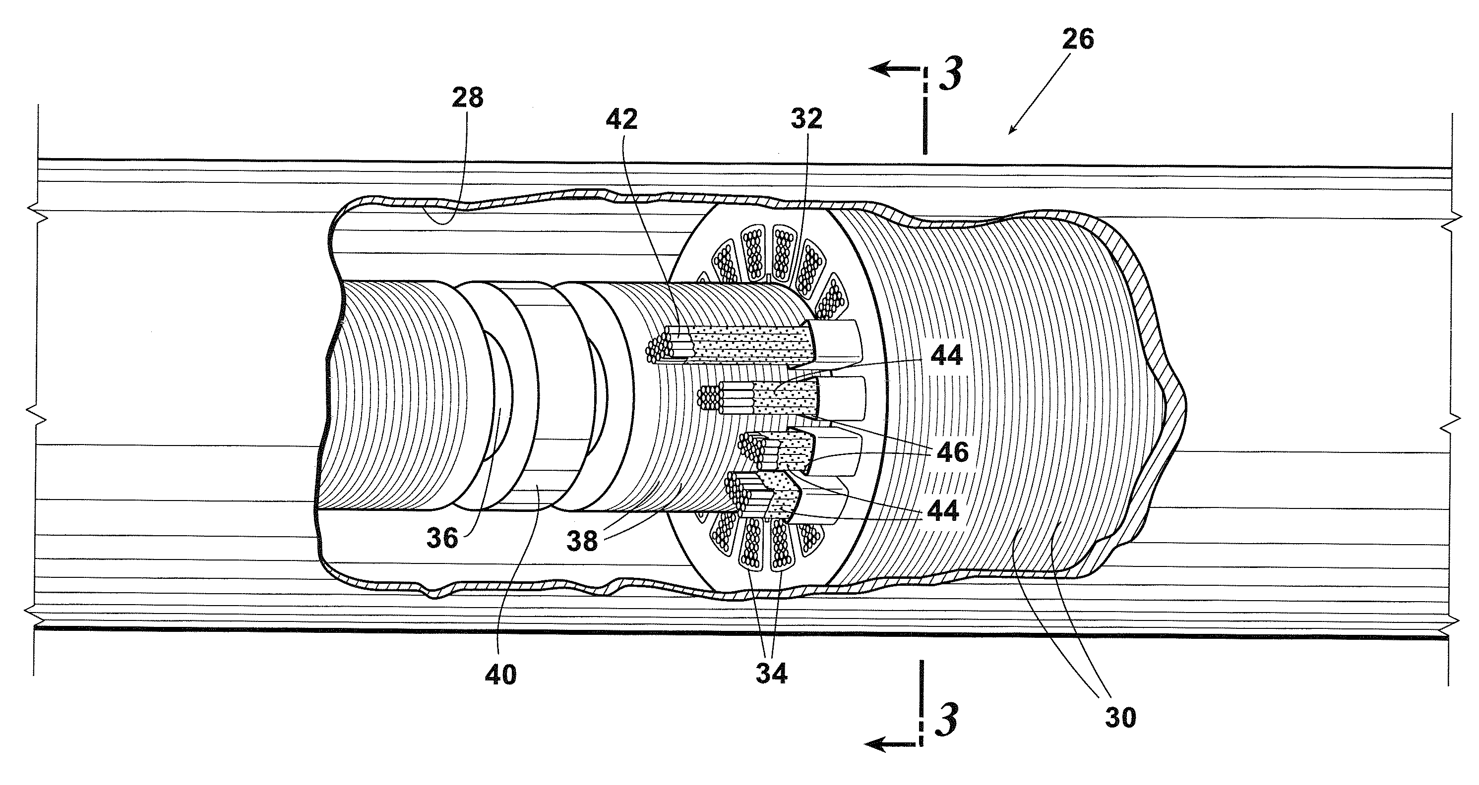
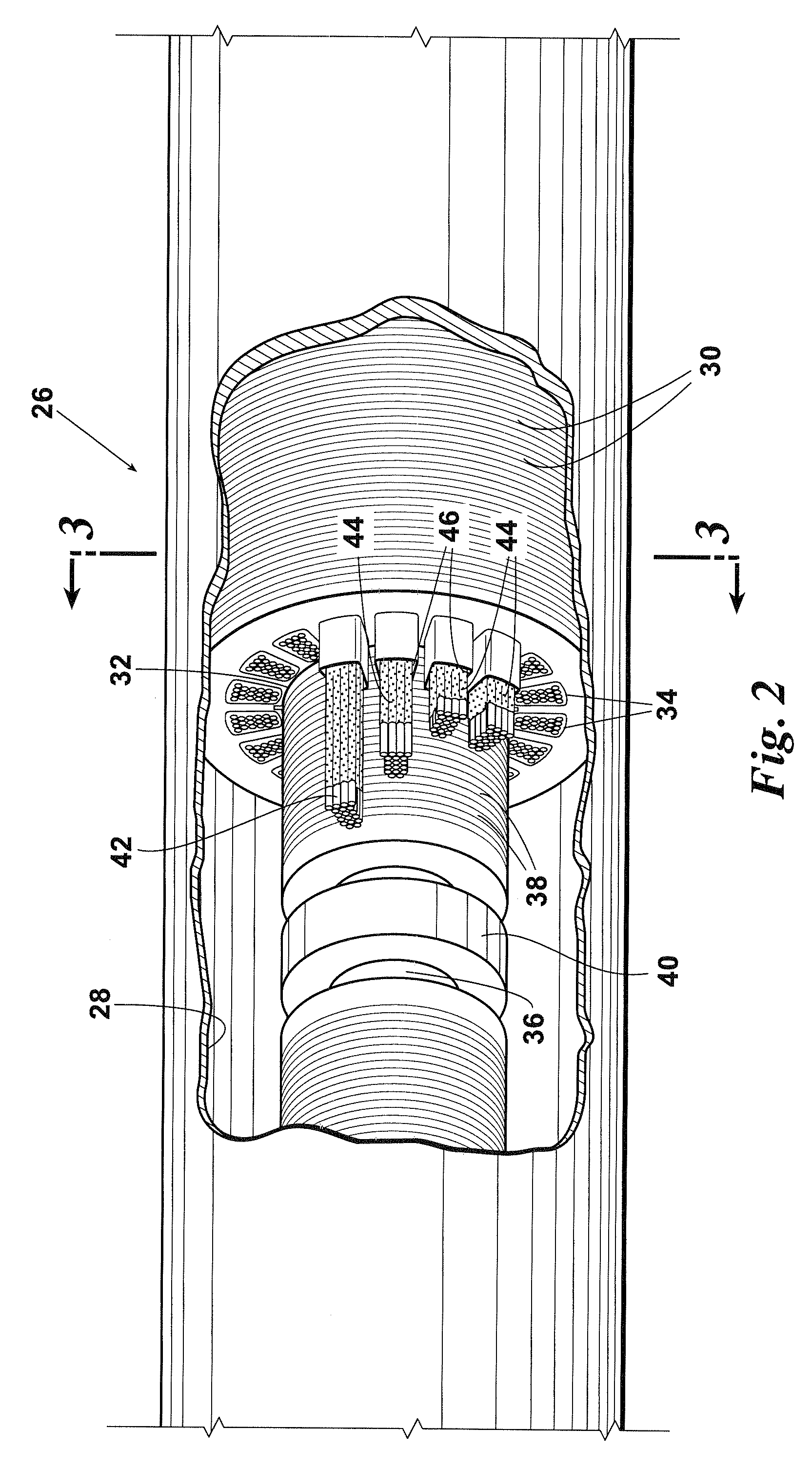
[0017]Referring now primarily to FIGS. 2 and 3, electrical motor 26 comprises a housing 28 and a plurality of stator laminations 30. Stator laminations 30 each define a central orifice 32 (FIG. 3) and a plurality of wire orifices or lamination slots 34. A shaft 36 passes through central orifice 32 of the plurality of stator laminations 30.

[0018]A plurality of rotors 38 are mounted on shaft 36. Rotors 38 rotate within a central space defined by the central orifice 32 of each of the plurality of stator laminations 30. R...


PUM

PropertyMeasurementUnit
Temperatureaaaaaaaaaa
Shrinkageaaaaaaaaaa
Heataaaaaaaaaa

Abstract

An electrical motor for an electrical submersible pump wherein the electrical motor has increased heat transfer capabilities. The electrical motor includes a housing and a plurality of stator laminations within the housing. Each stator lamination defines a central orifice and a plurality of lamination slots. A plurality of magnet wires pass through each of the plurality of lamination slots formed by the stacked plurality of stator laminations. Shrink wrap surrounds each of the plurality of magnet wires to secure the magnet wires in bundles. The result is that the wires are effectively bound together in a manner that allows oil to move freely inside the lamination slots surrounding the wire bundles. Since fluid can pass between and around the windings, the overall winding temperature will be normalized, essentially reducing hot spots that occur in prior art designs.

Description

FIELD OF THE INVENTION[0001]The invention relates generally to the field of electrical submersible pump motors. More particularly, the invention relates to increasing heat transfer for cooling electrical submersible pump motors.BACKGROUND OF THE INVENTION[0002]In an electrical submersible pumping unit, an electric submersible motor is typically used to drive an attached centripetal pump. The electrical submersible pump unit is placed down the well bore of an oil well and is used to push oil to the surface.[0003]The motors are typically filled with a highly refined mineral oil or synthetic with high dielectric strength. The design and operating voltage of these motors typically range from 230 volt up to 7,200 volts. Amperage requirement typically varies from 12 to 200 amps. The required horsepower may be achieved by increasing the length, or diameter, of the motor section. Larger single motor assemblies have been known to exceed 100 feet in length and rated up to 400 horsepower, whil...

Claims


Application Information

Patent Timeline
IPC IPC(8): F04D13/08B65B53/02H01B3/30H02K5/132F04B35/04
CPCF04D13/10H02K5/132H02K3/44H02K3/34
Inventor PARMETER, LARRY J.KNAPP, JOHN M.
Owner BAKER HUGHES INC
Why Eureka
Try Eureka