Coil Integrated Inductor

a coil integrated inductor and integrated inductor technology, applied in the direction of inductance, inductance with magnetic core, inorganic material magnetism, etc., can solve the problems of structural unbalance, insufficient insulation between the electrodes and/or the core and the magnetic body, and limited mechanical strength of the binder used in the conventional coil integrated inductor, etc., to achieve the effect of increasing not only the surface resistance of the magnetic body, but also the mechanical strength of the magnetic body

Inactive Publication Date: 2009-04-09
IRKUTSK STATE UNIVERSITY
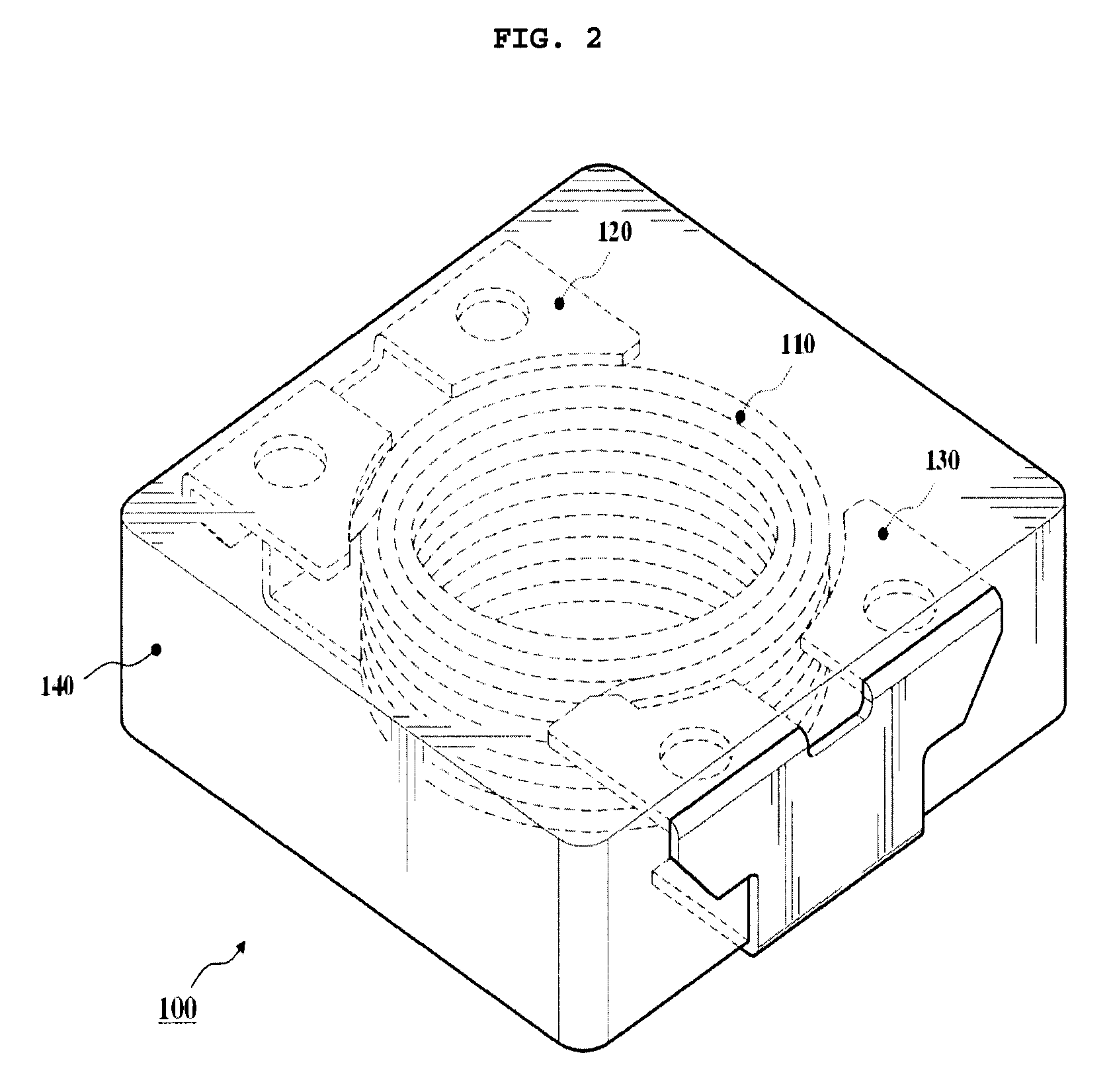
View PDF3 Cites 21 Cited by
  • Summary
  • Abstract
  • Description
  • Claims
  • Application Information

AI Technical Summary

Benefits of technology

[0009]The present invention is based on the finding that adding epoxy silane to a magnetic composition for preparation of a magnetic body of an inductor can increase not only the surface resistance of the magnetic body, but also the coupling strength between an organic binder and an inorganic metallic magnetic material, resulting in higher mechanical strength of the magnetic body.
[0010]Accordingly, the present invention has been made to solve the above-mentioned problems occurring in the prior art, and the present invention provides a coil integrated inductor which has higher surface resistance and improved mechanical strength.

Problems solved by technology

However, in the above described coil integrated inductor, the buried electrode portions (internal electrodes) are in direct contact with the magnetic body, so that insufficient insulation between the electrodes and / or the core and the magnetic body is inevitable.
Furthermore, the binder used in the conventional coil integrated inductor has limited ability in increasing the mechanical strength.
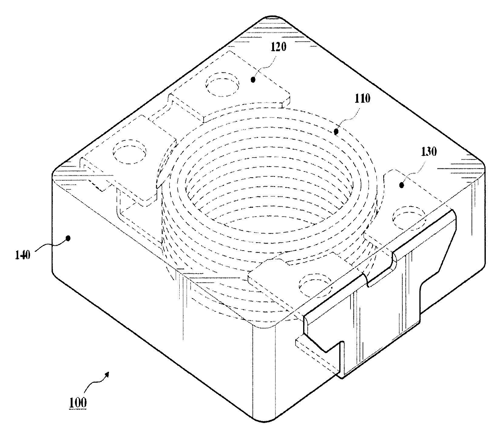
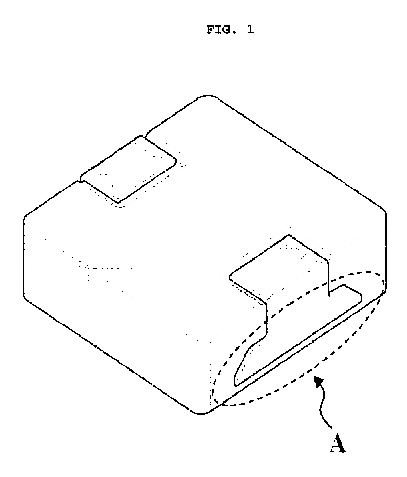
Besides, as indicated by reference character A in FIG. 1, portions of electrodes of the inductor are disposed on and coupled to specific surfaces of the magnetic body, so that they are structurally unbalanced, with the result of a problem occurring in that the mechanical strength thereof is very low at those portions.

Method used


Image

  • Coil Integrated Inductor
  • Coil Integrated Inductor
  • Coil Integrated Inductor

Examples


examples

[0061]In this preferred embodiment, the magnetic compositions for preparation of the magnetic bodies included Carbonyl Iron Powder as the magnetic powder, binder (product name: ‘Vinylresol resin’) described in Table 1 and epoxy silane (C9H2O5Si), each having the content shown in Table 2 (weight percent based on the weight of the magnetic powder) below, and Zinc as lubrication material having the amount of 0.2 weight percent, was used.

[0062]Coil integrated inductors having the dimensions of 10 mm×10 mm×3 mm were prepared according to the process shown in FIG. 12. Table 2 shows the surface resistances and mechanical strength of the manufactured inductors.

[0063]The surface resistance was obtained through the measurement of resistance between the external electrodes and the top surface of the magnetic body. The mechanical strength was obtained through the measurement of the bending strength value thereof after a bar-shaped workpiece having dimensions of 20 mm×10 mm×5 mm had been manufac...


PUM

PropertyMeasurementUnit
weight percentaaaaaaaaaa

Abstract

Disclosed is a coil integrated inductor. The coil integrated inductor includes a coil wound a predetermined number of times, electrodes joined to respective ends of the coil, and a magnetic body integrated with the coil and internal electrodes of the electrodes, in which the magnetic body includes magnetic powder, an organic binder and epoxy silane. When the magnetic body is formed, the mixed magnetic material including epoxy silane is used, so that the surface resistance and mechanical strength of the inductor according to the present invention can be remarkably increased.

Description

BACKGROUND OF THE INVENTION[0001]1. Field of the invention[0002]The present invention relates to a coil integrated inductor.[0003]2. Description of the Prior Art[0004]As generally known in the art, a conventional inductor includes an internally wound coil, electrodes respectively connected to both ends of the coil, and a composite magnetic body (hereinafter referred to as a magnetic body′) integrated with the coil and electrodes. The magnetic body is generally fabricated with the mixture of powered metallic magnetic material, such as sendust, iron or permalloy, and an uncured organic binder. The organic binder helps to increase the mechanical strength of a core itself, and to increase the resistance of the core by being between the metallic magnetic particles.[0005]Since powdered sendust, iron and permalloy generally have high saturation magnetic flux density, they are not easily saturated by high current and provide an excellent current superposition characteristic. Such powder is ...

Claims


Application Information

Patent Timeline
Patent Type & Authority Applications(United States)
IPC IPC(8): H01F27/02
CPCH01F1/26H01F17/04H01F2017/048H01F41/0246H01F27/292
Inventor SHIN, JAE YOUNGKIM, KWANG YOUNGSONG, BYUNG MOOLEE, YONG JIN
Owner IRKUTSK STATE UNIVERSITY
Why Eureka
Try Eureka