Laser measuring device

a technology of laser and measuring device, which is applied in the direction of distance measurement, instruments, surveying instruments, etc., can solve the problems of limited use, drawbacks of space sensors according to this measuring system, and methods that are not suitable for long distance measurement, etc., and achieves the effect of simple structure and convenient handling

Inactive Publication Date: 2009-04-09
SAMSUNG ELECTRO MECHANICS CO LTD
View PDF9 Cites 3 Cited by
  • Summary
  • Abstract
  • Description
  • Claims
  • Application Information

AI Technical Summary

Benefits of technology

[0015]The present invention has been made to solve the foregoing problems with the prior art, and therefore the present invention provides a laser measuring device for precisely measuring a short distance, which is obtained by adding a relatively simple structure to a TOF laser measuring device that is simple and easily handled.
[0022]The laser measuring device of the invention is a TOF measuring device that has a simple structure and is easily handled, and also can use an optical fiber, optical mirrors or a prism to extend the optical path in order to more precisely measure a short distance, thereby ensuring the reliability of a product.

Problems solved by technology

Of these sensors, space sensors using the RF or supersonic wave are merely applicable to the recognition of a space in a short distance (several meters) owing to poor convergence and spatial resolution.
While the triangulation has excellent precision in short distance measurement, this method is not suitable for long distance measurement since a measurement error increases in proportion to the measuring distance.
That is, a space sensor according to this measuring system has drawbacks such as limited use and high price even though it can measure the object with a very high precision of, for example, several millimeters (mm).
That is, since light can travel 30 cm at about 1 ns, high performance for detecting several nanoseconds is required to measure a distance less than 1 m. For more precise measurement, an expensive large size device is required.

Method used


Image

  • Laser measuring device
  • Laser measuring device
  • Laser measuring device

Examples


Embodiment Construction

[0031]The present invention will now be described more fully with reference to the accompanying drawings, in which exemplary embodiments thereof are shown. This invention may, however, be embodied in many different forms and should not be construed as limited to the embodiments set forth herein. Rather, these embodiments are provided so that this disclosure will be thorough and complete, and will fully convey the scope of the invention to those skilled in the art.

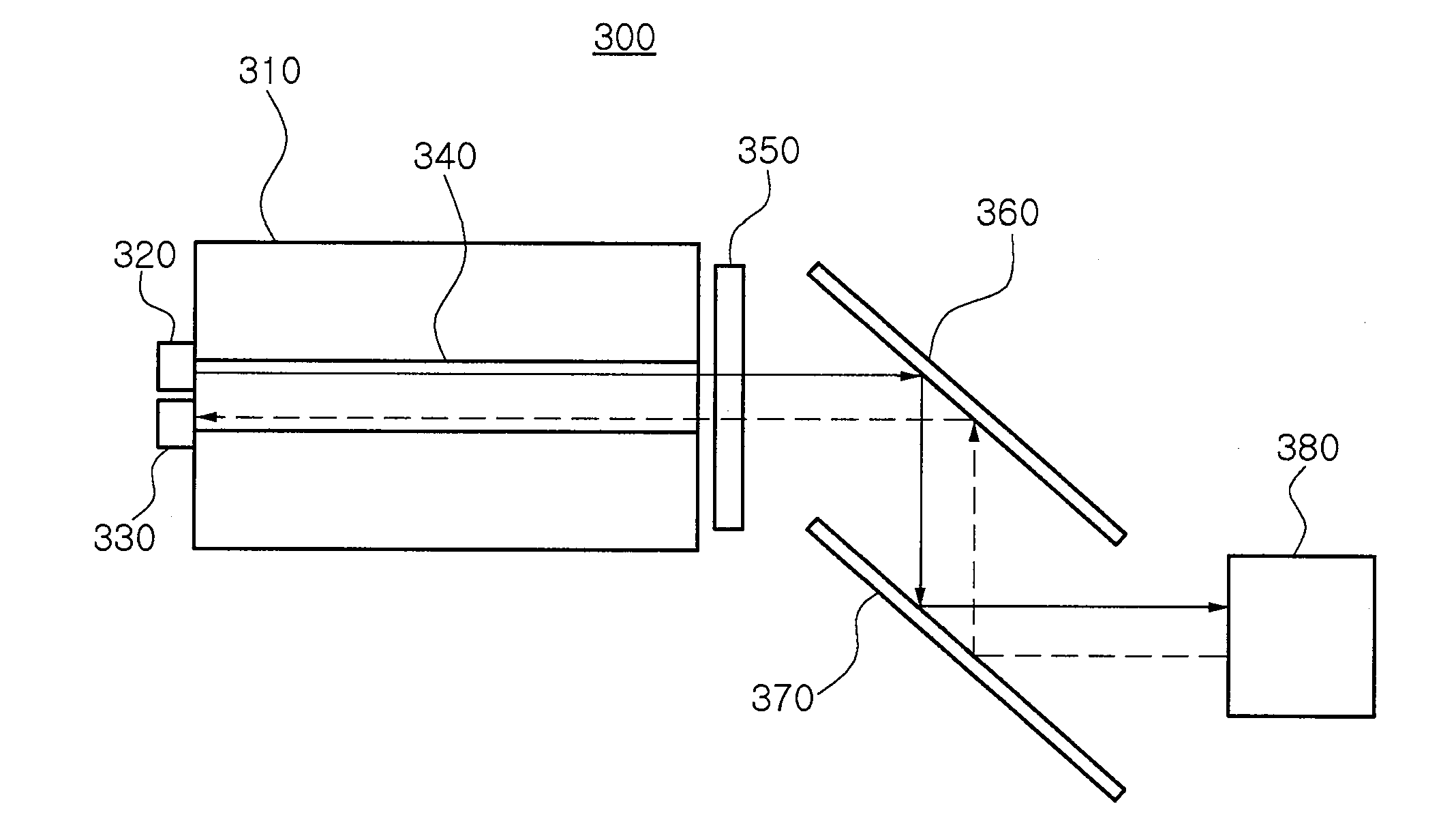
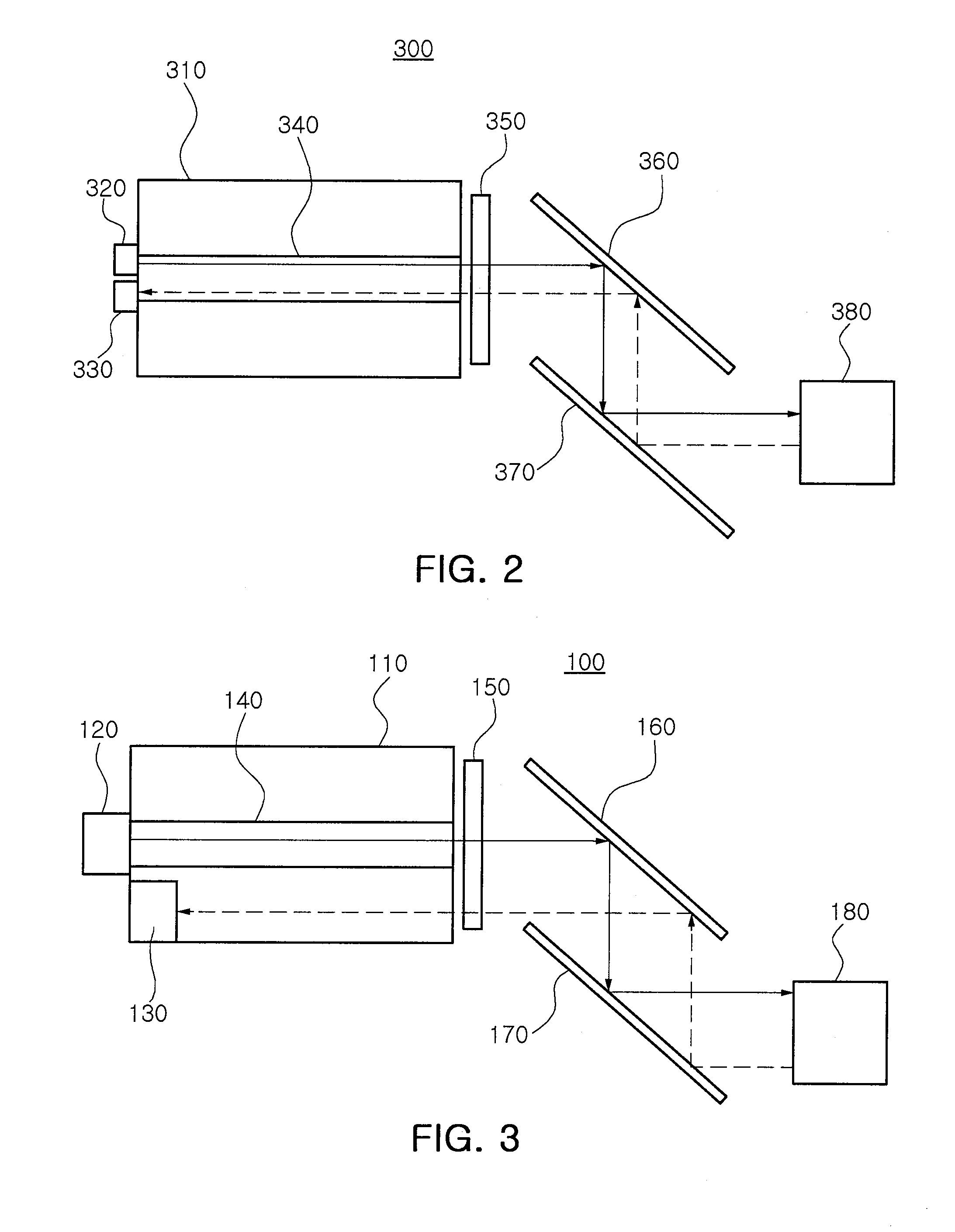
[0032]FIG. 2 is a configuration view illustrating a laser measuring device 100 according to an embodiment of the invention. The laser measuring device 100 of this embodiment includes a light emitter 120 for emitting light, a band pass filter 150 for allowing incident light to pass, which has a wavelength the same as that of emitted light, a light receiver 130 for receiving incident light, which is allowed to pass through the band pass filter 150, and an optical path extender 140 for extending an optical path of at least one...


PUM


Abstract

A laser measuring device for precisely measuring a short distance is obtained by adding a relatively simple structure to a TOF laser measuring device that is simple and easily handled. The laser measuring device includes a light emitter, a light receiver and an optical length extender, which increases an optical path of emitted light or incident light.

Description

CROSS-REFERENCE TO RELATED APPLICATIONS[0001]The present application is based on and claims priority from Korean Application No. 2007-100361, filed on Oct. 5, 2007, the disclosure of which is hereby incorporated by reference herein in its entirety.BACKGROUND OF THE INVENTION[0002]1. Field of the Invention[0003]The present invention relates to a laser measuring device, and more particularly, to a laser measuring device for precisely measuring a short distance, which is obtained by adding a relatively simple structure to a Time-Of-Flight (TOF) laser measuring device that is simple and easily handled.[0004]2. Description of the Related Art[0005]Space / object sensors for detecting three dimensional space and object can be divided into contact and non-contact sensors. Contact sensors are generally used in standard environments such as a factory, a building and an industrial site, whereas non-contact sensors can also be flexibly applied to non-standard environments in which various objects...

Claims


Application Information

Patent Timeline
Patent Type & Authority Applications(United States)
IPC IPC(8): G01C3/08
CPCG01B11/026G01S17/10G01S7/4818G01S7/4814G01C3/00G01C15/00G01B11/00
Inventor KIM, HONG KIKIM, BAE KYUNPARK, JUNE SIKKANG, DONG HOONHONG, SANG SULEE, CHANG YUNKIM, TAK GYUM
Owner SAMSUNG ELECTRO MECHANICS CO LTD
Why Eureka
Try Eureka