
Correlator

a correlation spectroscopy and sample method technology, applied in chemical methods analysis, instruments, material analysis, etc., can solve the problems of linear sampling method, reduced accuracy, and difficulty in wide-range particle size use, so as to improve the accuracy of the autocorrelation function

Active Publication Date: 2009-04-09
HORIBA LTD
View PDF0 Cites 5 Cited by
  • Summary
  • Abstract
  • Description
  • Claims
  • Application Information

AI Technical Summary

Benefits of technology

The present invention is a correlator that improves the accuracy of the autocorrelation function by integrating the linear sampling method, the exponential sampling method, and the multi-tau sampling method. The correlator includes a counter, a sampling part, a delay part, an operation part, and a control part. The control part sets the delay time or the sampling time for each channel based on a recurrence formula or a combination of different recurrence formulas. The invention can handle polydisperse systems with a wide measurement range and can improve the accuracy of the autocorrelation function while enabling the measurement over a wide range.

Problems solved by technology

However, these methods respectively have the following problems:
Also, even if the number of channels is sufficient for calculation, the sampling time should be adjusted depending on a particle size, resulting in the trade-off between the number of channels and an accuracy or time-consumption, and therefore the linear sampling method has a problem of practical difficulty in the use for the wide range of particle sizes.
However, in practice, the method has a problem that increasing the sampling time leads to a shortage of the number of data points on small particles, resulting in a reduction in accuracy, or the like.
Further, the multi-tau method is, as described in Patent document 1, one in which all channels are divided into blocks, and by linear sampling for channels in each of the blocks and exponential sampling between the blocks, the shortcomings of the above both methods are overcome and the advantages of the both are adopted, but has a problem that for a channel having a longer interval in a later stage block, a base line fluctuation, i.e., so-called bias noise, is increased, resulting in a reduction in accuracy of the autocorrelation function.

Method used


Image

  • Correlator
  • Correlator
  • Correlator

Examples


first embodiment

Effect of First Embodiment

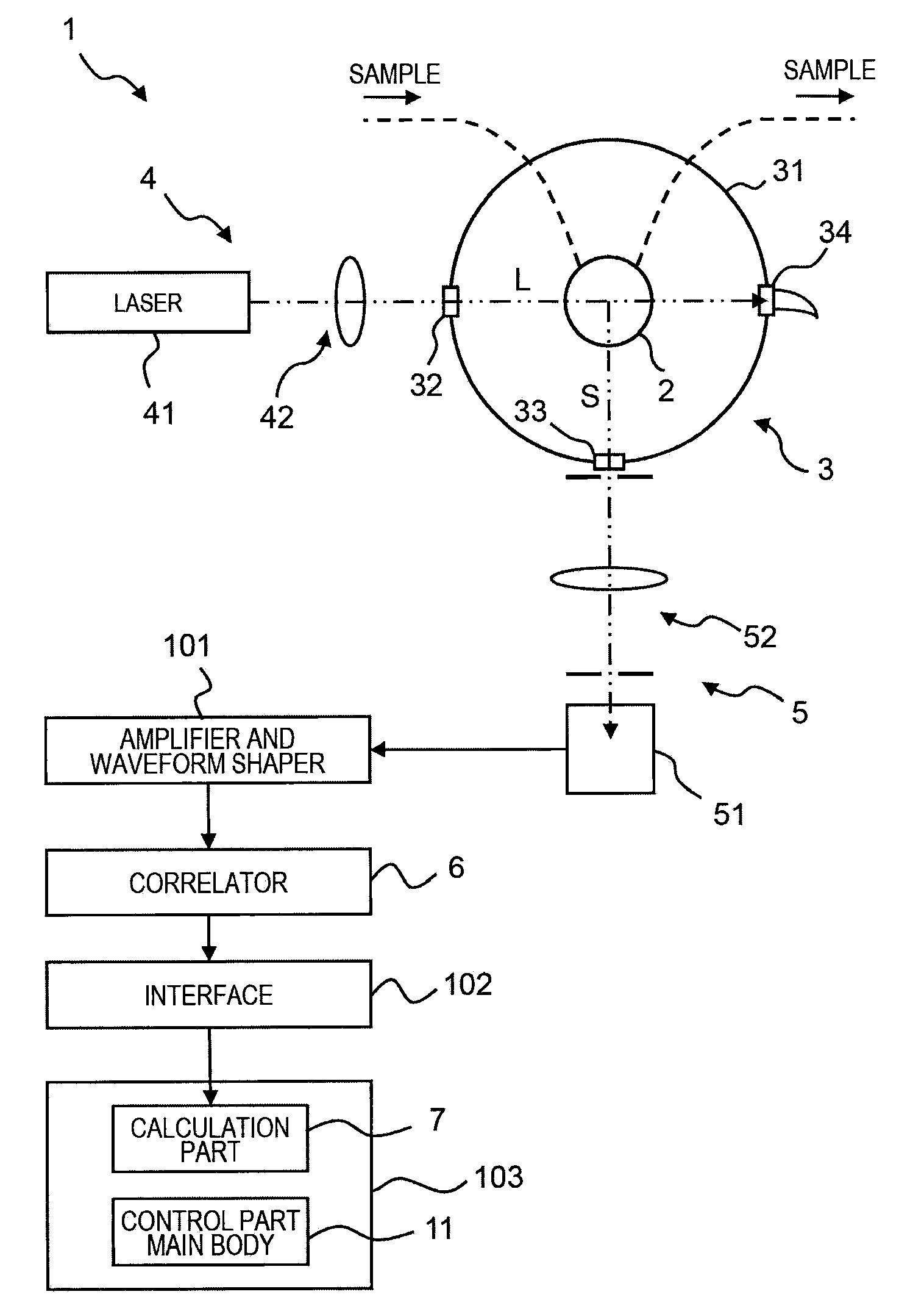
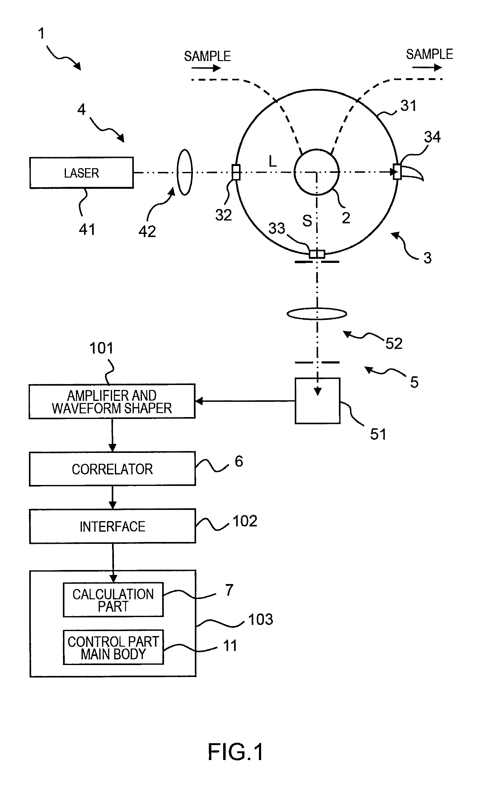
[0047]According to the particle size analyzer 1 relating to the present embodiment configured as above, a larger number of data points can be obtained as compared with the conventional exponential sampling method. Also, if the number of channels is fixed, a time close to an optimum delay time can be expressed, and therefore an accuracy of the autocorrelation function and a measurement result can be improved and a circuit can be simplified. Further, the sampling is performed with the delay time having a natural number, and therefore there is no missing or overlap count of the pulse signal. This is the most important issue in the photon correlation method in which information on a diffusion coefficient due to the Brownian movement is obtained from a random signal, and a crucial requirement particularly in the case of a sparse measuring object. Also, effects of being able to simplify the device and increasing the degree of freedom of measurement are produced.

second embodiment

[0048]Next, a second embodiment of the particle size analyzer using the correlator of the present invention is described.

[0049]The particle size analyzer of the present embodiment is different from that of the first embodiment in terms of the delay time in the delay part 63 of the correlator. The control part 65 of the present embodiment is one for setting the delay time Tn in the delay part 63 on a basis of the three-term recurrence formula other than that for the Fibonacci sequence.

[0050]That is, the control part 65 determines the delay time according to a following expression:

Tn=fn×To,fn=fn-1+fn-3(fn:naturalnumber).Here,fn=fn-1+fn-3=fn-1+(1 / r)fn-2=fn+1+(1 / r2)fn-1=(1+1 / r2)fn-1.

[0051]Accordingly, the sequence formed by the addition of the elements fn−1 and fn−3 of the geometric sequence with a ratio of r, i.e., fn=fn−1+fn−3, can be considered as a geometric sequence with a ratio of r13 (=1.4656) if r takes a real root r13 (=1.4656) of r2(r−1)−1=0. That is, a sequence {1, 1, 1, 2, 3...

third embodiment

[0053]Next, a third embodiment of the particle size analyzer using the correlator of the present invention is described.

[0054]The particle size analyzer of the present embodiment is different from that of the first embodiment in terms of the delay time in the delay part 63 of the correlator. The control part 65 of the present embodiment is one for setting the delay time Tn in the delay part 63 on a basis of the four-term recurrence formula.

[0055]That is, the control part 65 determines the delay time Tn according to the following expression:

Tn=fn×To,

fn=fn−1+fn−5+fn−6 (fn: natural number).

[0056]This sort of recurrence formula can cause a geometric ratio to converge to 1.42, and a geometric ratio of r=√2 to be asymptotically provide. Specifically, the sequence of {1, 1, 1, 1, 1, 1, 3, 5, 7, 9, 11, 15, 23, 35, 51, 71, 97, 135, 193, 279, 401, 569, 801, 1129, . . . } can be obtained. This calculation result may be used as the sampling time without modification, or may be used to determine...


PUM

PropertyMeasurementUnit
timeaaaaaaaaaa
delay timeaaaaaaaaaa
sampling time Tnaaaaaaaaaa

Abstract

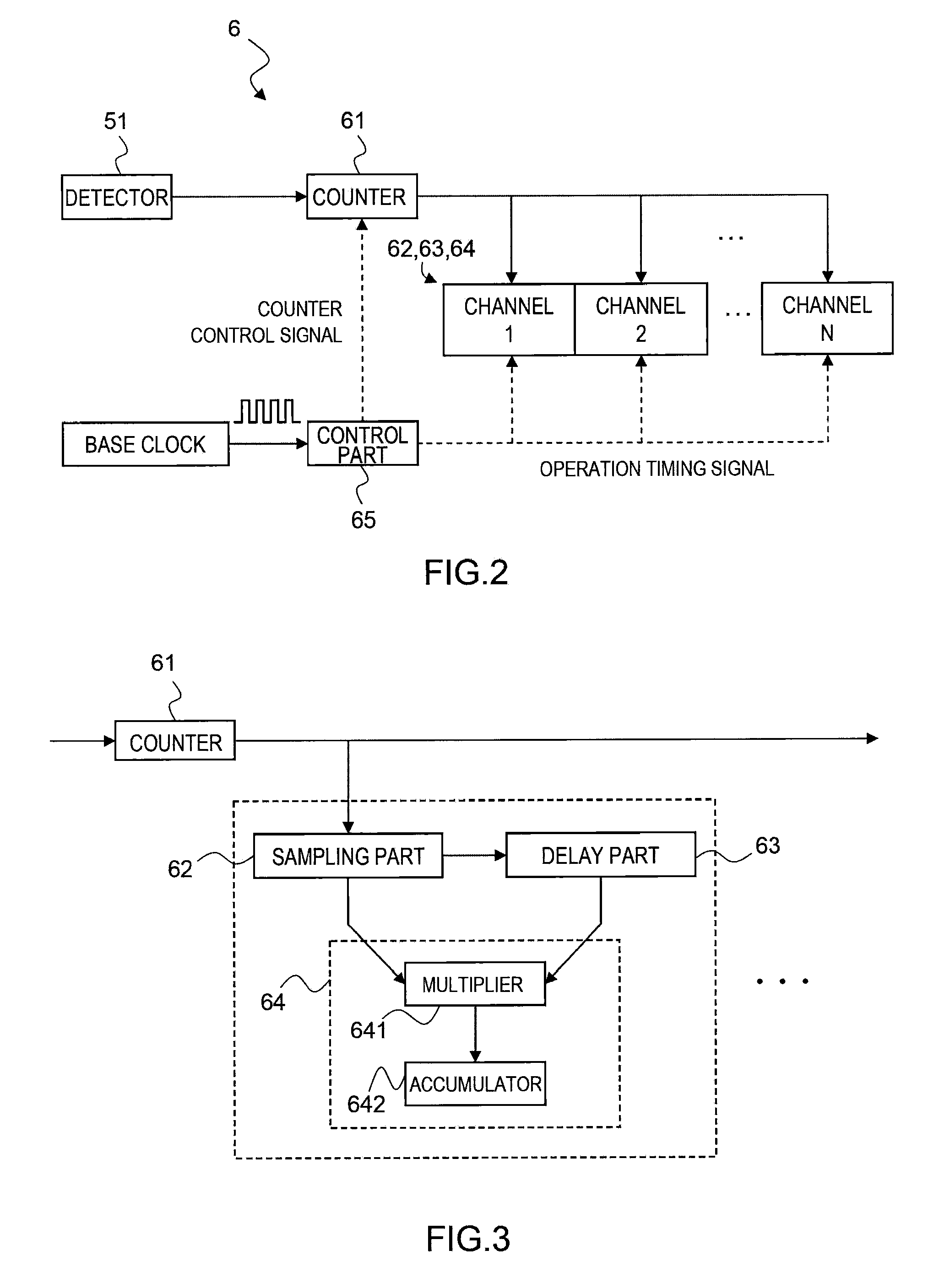
In order to improve an accuracy of an autocorrelation function, a correlator comprises a counter 61 for receiving a pulse signal at given time intervals (sampling times) and counting the number of pulses; a shift register 63 for receiving the number of pulses counted by the counter 61 and performing sequential time delay; an operation part 64 for performing a product-sum operation of an output from the counter 61 and that delayed by the shift register 63 for each channel; and a control part 65 for setting a delay time or a sampling time by the shift register 63 on a basis of a relationship of the Fibonacci sequence.

Description

BACKGROUND OF THE INVENTION[0001]1. Field of the Invention[0002]The present invention relates to a sampling method in a photon correlation spectroscopy used for, for example, a particle size analyzer or the like.[0003]2. Description of the Background Art[0004]In measurements of particle size distribution based on the photon correlation spectroscopy (PCS), in addition to counting the number of photons (pulse signal) at a given sampling time depending on a scattered light intensity arising from particles to be measured, time is delayed with a shift register; a product-sum operation is performed to obtain an autocorrelation function; and a particle size (particle diameter) is calculated from a relaxation coefficient of the function.[0005]Also, as the sampling method, a linear sampling method, exponential sampling method, multi-tau method, and the like are known.[0006]However, these methods respectively have the following problems:[0007]The autocorrelation function obtained by the photo...

Claims


Application Information

Patent Timeline
Patent Type & Authority Applications(United States)
IPC IPC(8): G01N15/02
CPCG01N15/0205
Inventor YAMAGUCHI, TETSUJIKAWARABAYASHI, SHIGEYUKI
Owner HORIBA LTD
Learn More