Eureka AIR delivers breakthrough ideas for toughest innovation challenges, trusted by R&D personnel around the world.

Circumferential ablation guide wire system and related method of using the same

a guide wire and circumferential ablation technology, applied in the field of circumferential ablation guide wire systems, can solve the problems of low success rate, high prevalence of atrial fibrillation, significant morbidity, mortality and cost, and blunted excitement for contemporary catheter ablation techniques and equipment, so as to improve safety and procedural success, improve atrial contact, and reduce traumatic

Active Publication Date: 2009-04-09
CROSSMAN ARTHUR W
View PDF66 Cites 36 Cited by
  • Summary
  • Abstract
  • Description
  • Claims
  • Application Information

AI Technical Summary

Benefits of technology

[0006]The various embodiments of the present invention device and method significantly improves the safety and procedural success of the existing art by being able to be less traumatic to vascular tissue, improving atrial contact with the ablation surface, improving positioning and geometrical precision of the ablation pattern, improving steerability and deliverability of the ablation device and by improving localization and geometric precision of the ablation device. The risk of pulmonary vein fibrosis / stenosis will also be substantially lowered. Finally, expansion of the eligible atrial fibrillation population will inherently increase due to the improved components and methods of the present invention.

Problems solved by technology

Atrial fibrillation is a highly prevalent arrhythmia associated with significant morbidity, mortality and cost.
Unfortunately excitement for contemporary catheter ablation techniques and equipment have been blunted by low success rates in a low risk patient populations as well resulting complications such as pulmonary vein fibrosis / stenosis and vascular trauma.

Method used


Image

  • Circumferential ablation guide wire system and related method of using the same
  • Circumferential ablation guide wire system and related method of using the same
  • Circumferential ablation guide wire system and related method of using the same

Examples


Embodiment Construction

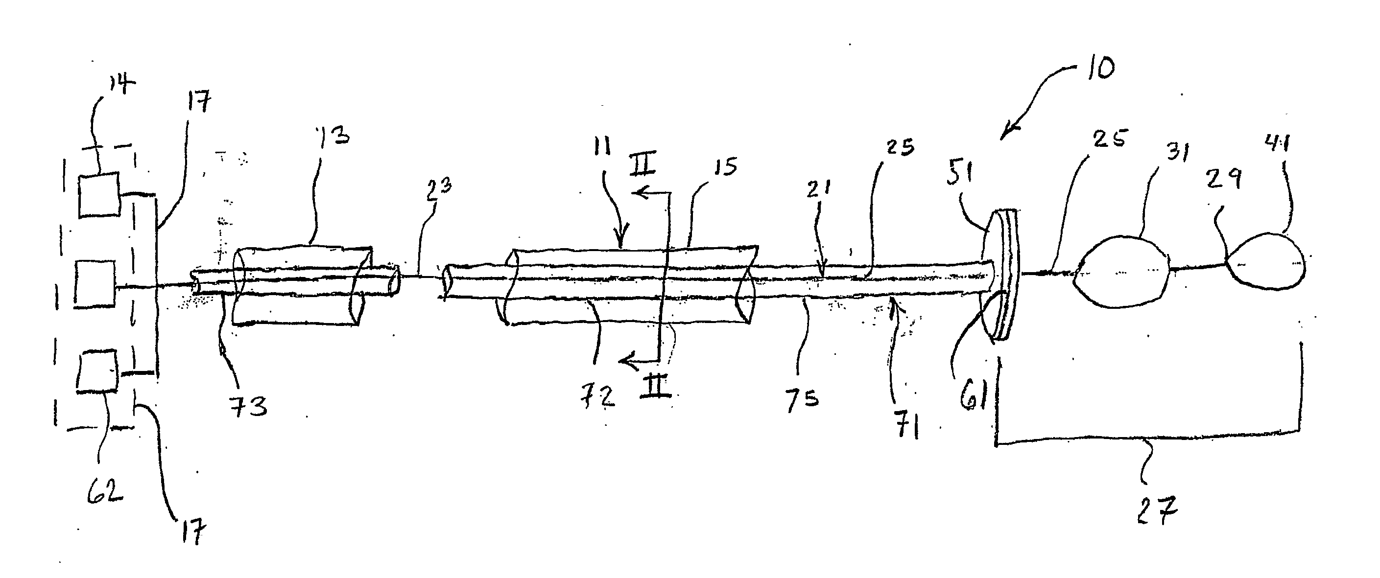
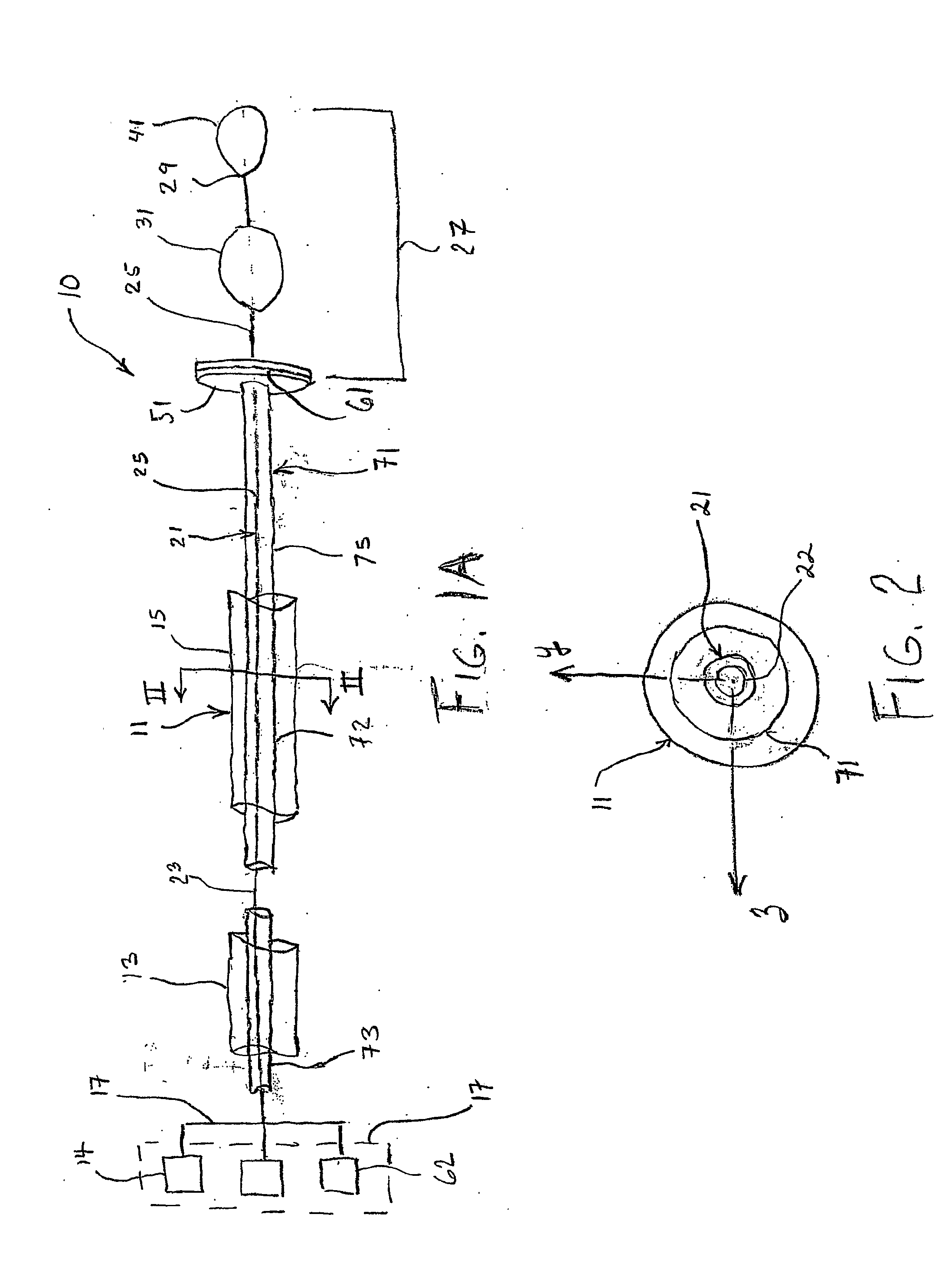
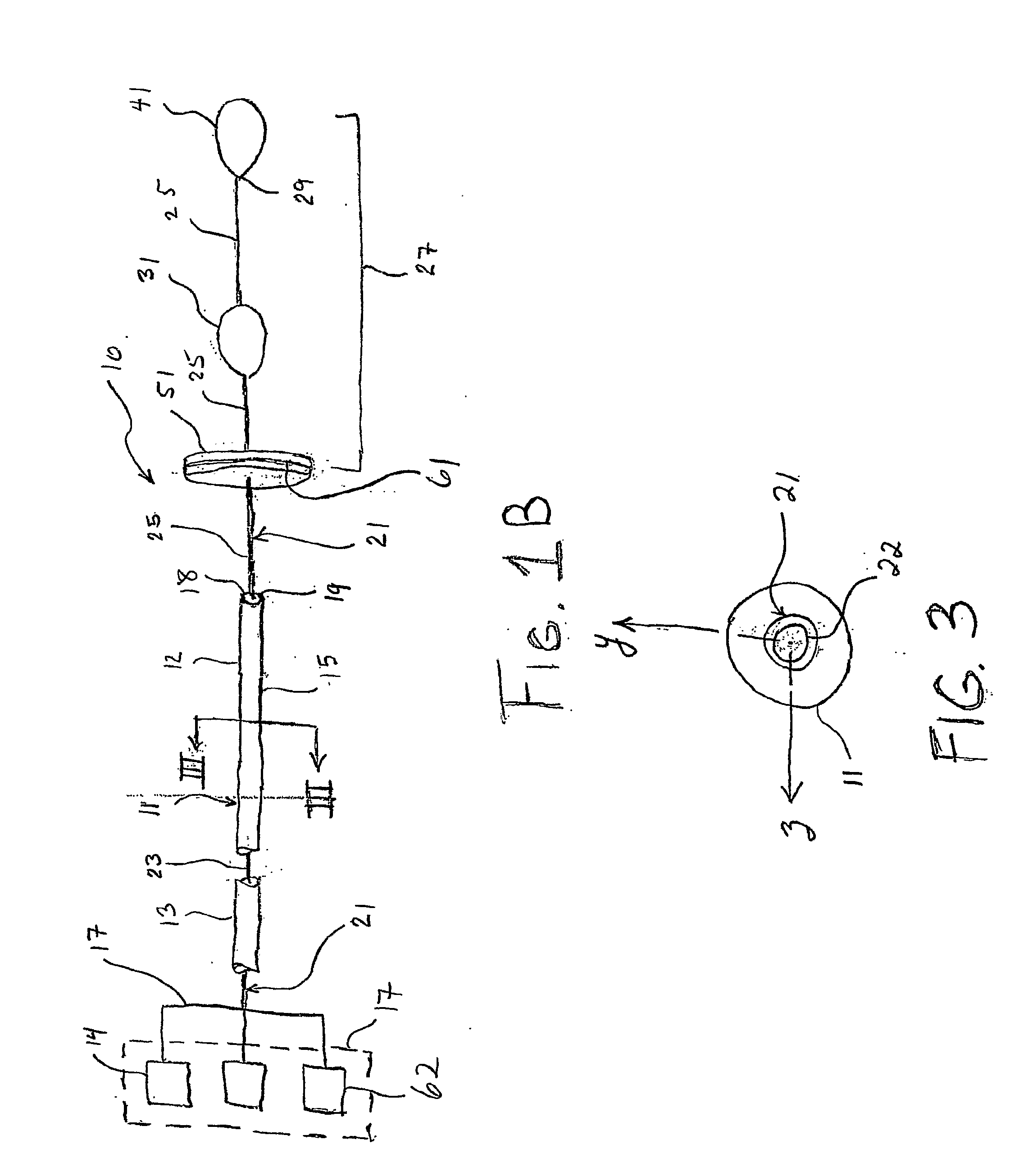
[0032]Turning to FIG. 1(A), FIG. 1(A) illustrates a schematic elevation view of an embodiment of the present invention ablation assembly 10 including a delivery catheter 71 having a delivery catheter shaft 72 with a proximal portion 73, distal portion 75, and an operator device 17. The delivery catheter 71 travels coaxially through a guide catheter 11 having a catheter shaft 12 with a proximal portion 13 and distal portion 15. The delivery catheter 71 accommodates a guide wire 21 that coaxially travels through the delivery catheter 71 to be inserted into a left atrium (LA) of the heart (not shown), or at a location of the vasculature as required or desired. The guide wire 21 can be used to cross the septum itself (with or without the guide catheter and / or delivery catheter) or act as a positioning mechanism, which will be discussed in greater detail below. The guide wire 21 includes a proximal portion 23 and distal portion 25 of the guide wire 21, and a distal tip 29, centering / alig...


PUM


Abstract

Device and method significantly that improves the safety and procedural success of the existing art by being able to be less traumatic to vascular tissue, improving atrial contact with the ablation surface, improving positioning and geometrical precision of the ablation pattern, improving steerability and deliverability of the ablation device and by improving localization and geometric precision of the ablation device. The risk of pulmonary vein fibrosis / stenosis will also be substantially lowered. Finally, expansion of the eligible atrial fibrillation population will inherently increase due to the improved components and methods of the present invention.

Description

RELATED APPLICATIONS[0001]The present patent application claims priority from U.S. Provisional Application Ser. No. 60 / 753,804, filed Dec. 24, 2005, entitled “Circumferential Ablation Guide Wire System and Related Method of Using the Same,” No. 60 / 780,627, filed Mar. 9, 2006, entitled “Circumferential Ablation Guide Wire System and Related Method of Using the Same,” and No. 60 / 800,522, filed May 15, 2006, entitled “Circumferential Ablation Guide Wire System and Related Method of Using the Same,” the entire disclosures of which are hereby incorporated by reference herein.BACKGROUND OF THE INVENTION[0002]Atrial fibrillation is a very common arrhythmia which accounts for a substantial amount of morbidity, mortality and costs. Specifically it can lead to death, stroke, transient ischemic attack, syncope, congestive heart failure, myocardial ischemia, myocardial infarction, palpitations, malignant arrhythmia, and altered mental status. Treatment options have traditionally consisted of an...

Claims


Application Information

Patent Timeline
Patent Type & Authority Applications(United States)
IPC IPC(8): A61B18/18A61B18/02
CPCA61B18/1492A61B2018/00261A61B2018/1435A61B2018/00375A61B2018/00285
Inventor CROSSMAN, ARTHUR W.
Owner CROSSMAN ARTHUR W
Why Eureka
Eureka Blog
Learn More