
Anti-skid control device and automatic brake control device

Active Publication Date: 2009-04-16
ADVICS CO LTD
View PDF19 Cites 13 Cited by
  • Summary
  • Abstract
  • Description
  • Claims
  • Application Information

AI Technical Summary

Benefits of technology

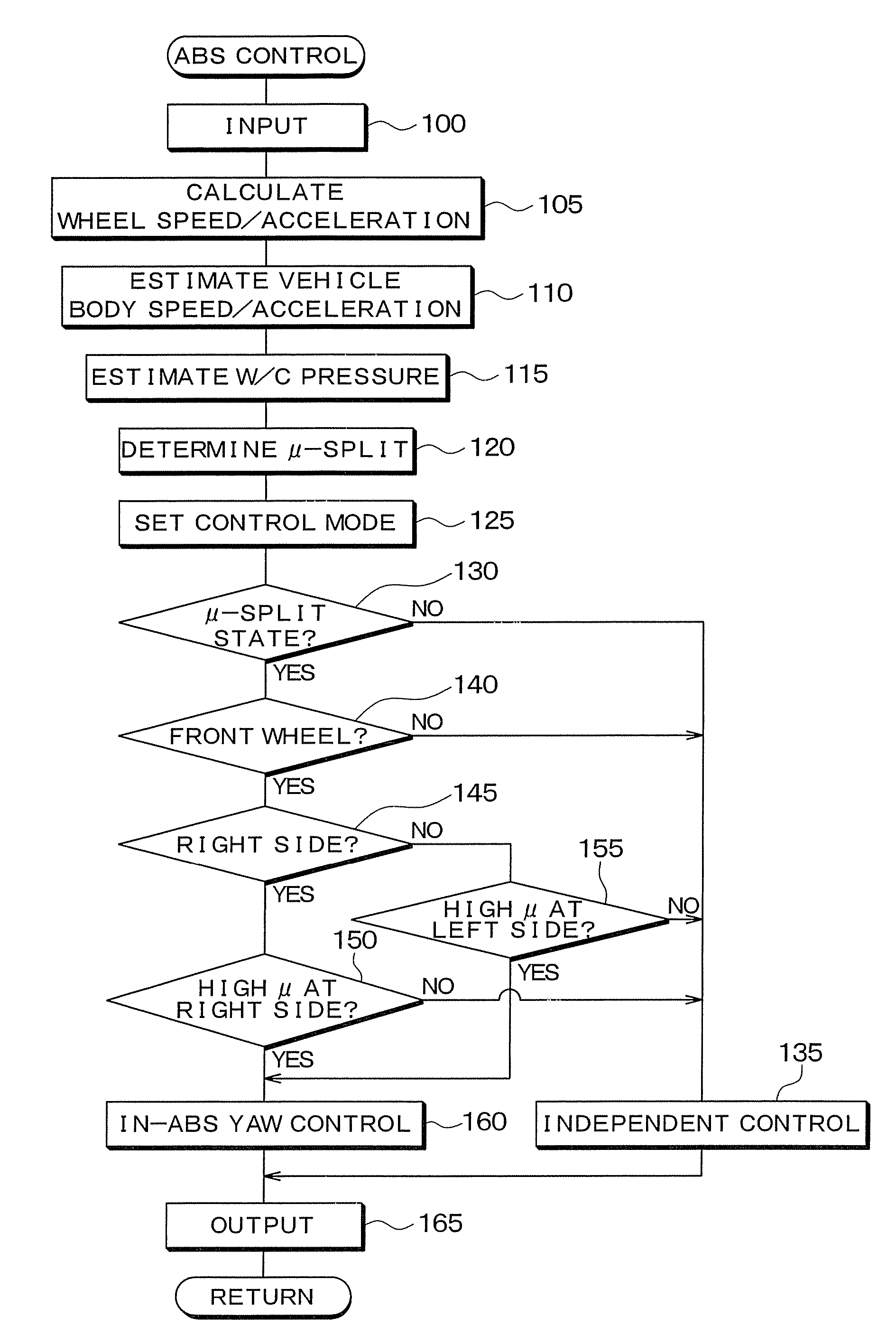
[0011]It is therefore an object of the present invention to provide an ABS control device for a vehicle which prevents the vehicle from slipping by making it possible to suppress the difference in the W / C pressure between the left front wheel and the right front wheel within a satisfactory range irrespective of the deviation in the characteristics of W / C pressure boosting caused by the individual variation of the boost control valve.
[0013]With this operation in which the differential pressure of the boost control valve is repeatedly switched between the first differential pressure and the second differential pressure, it becomes possible to reduce deviation of an expected value from an actual value of the difference in the W / C pressure between wheels. Therefore, it is possible to prevent the vehicle from slipping by suppressing the difference in the W / C pressure between the left front wheel and the right front wheel within a satisfactory range irrespective of the deviation in the characteristics of W / C pressure boosting caused by the individual variation of the boost control valve.
[0015]Thus, this anti-skid control device increases the W / C pressure for the wheel on the high-μ surface by switching repeatedly the differential pressure of the boost control valve for the front wheel on the high-μ surface between the first differential pressure and the second differential pressure. Therefore it is possible to suppress the deviation in the characteristics of W / C pressure boosting and to suppress the difference in the W / C pressure between the left front wheel and the right front wheel within a satisfactory range. As a result, it is possible to suppress the yaw torque applied to the vehicle and to prevent the vehicle from slipping.
[0016]The anti-skid control device may keep the differential pressure to be generated between the upstream side and the downstream side of the boost control valve for the wheel on the high-μ surface at the first differential pressure for a first period and after the first period at the second differential pressure for a second period.

Problems solved by technology

Therefore, it is difficult to keep the difference in the W / C pressure between the right side wheel and the left side wheel within a satisfactory range.
Therefore, unexpected yaw torque may be applied to the vehicle.
Especially, it is difficult to suppress the yaw torque to a satisfactory extent when the vehicle is running on the μ-split surface.
As a result, the spin of the vehicle cannot be effectively prevented.

Method used


Image

  • Anti-skid control device and automatic brake control device
  • Anti-skid control device and automatic brake control device
  • Anti-skid control device and automatic brake control device

Examples


first embodiment

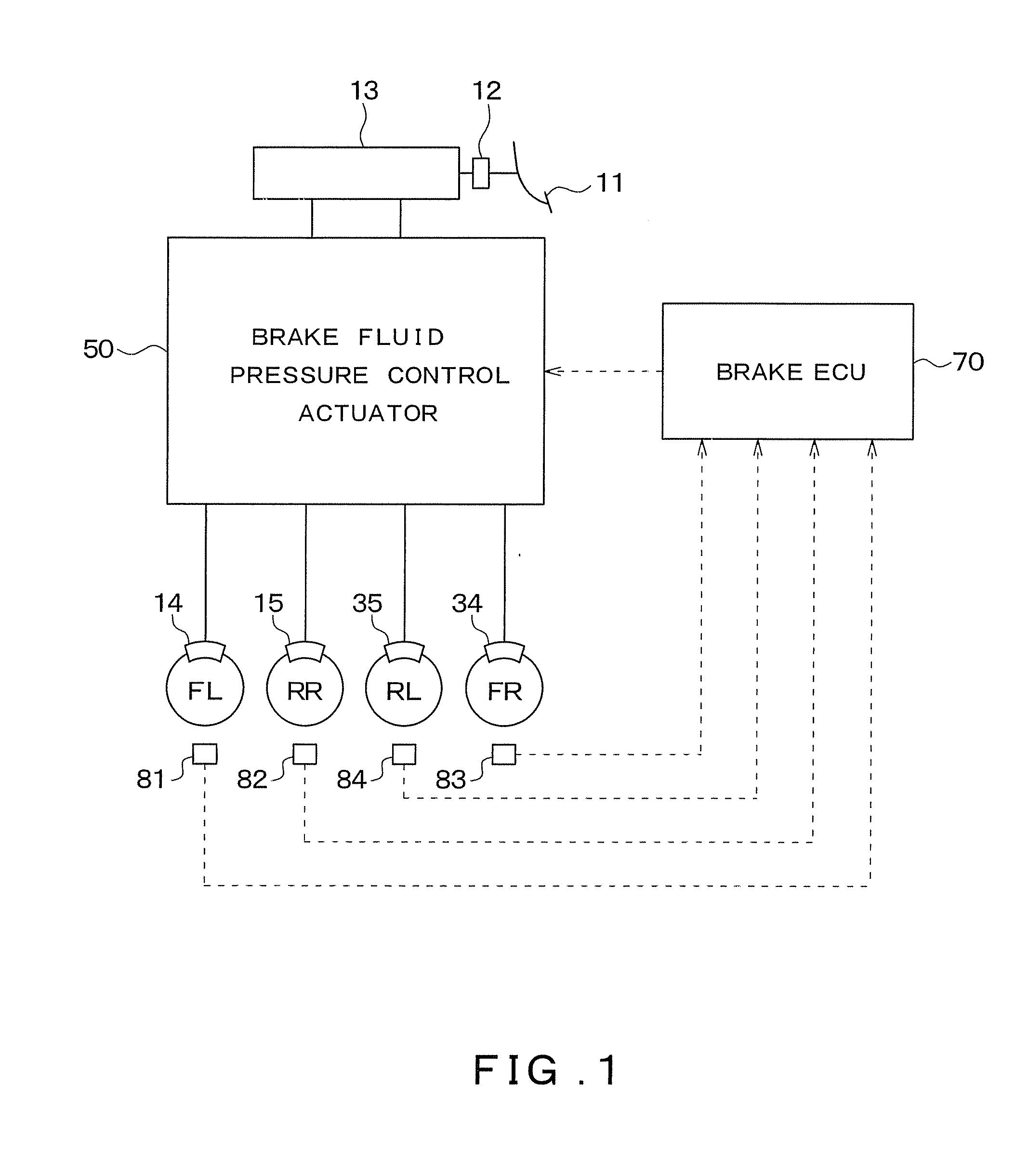
[0039]A first embodiment of the present invention is described. FIG. 1 is a block diagram showing functions of a brake control device 1 for a vehicle serving as an ABS control device according to the present embodiment. Specifically, a part of the brake control device 1 serves as the ABS control device when the part performs ABS control.

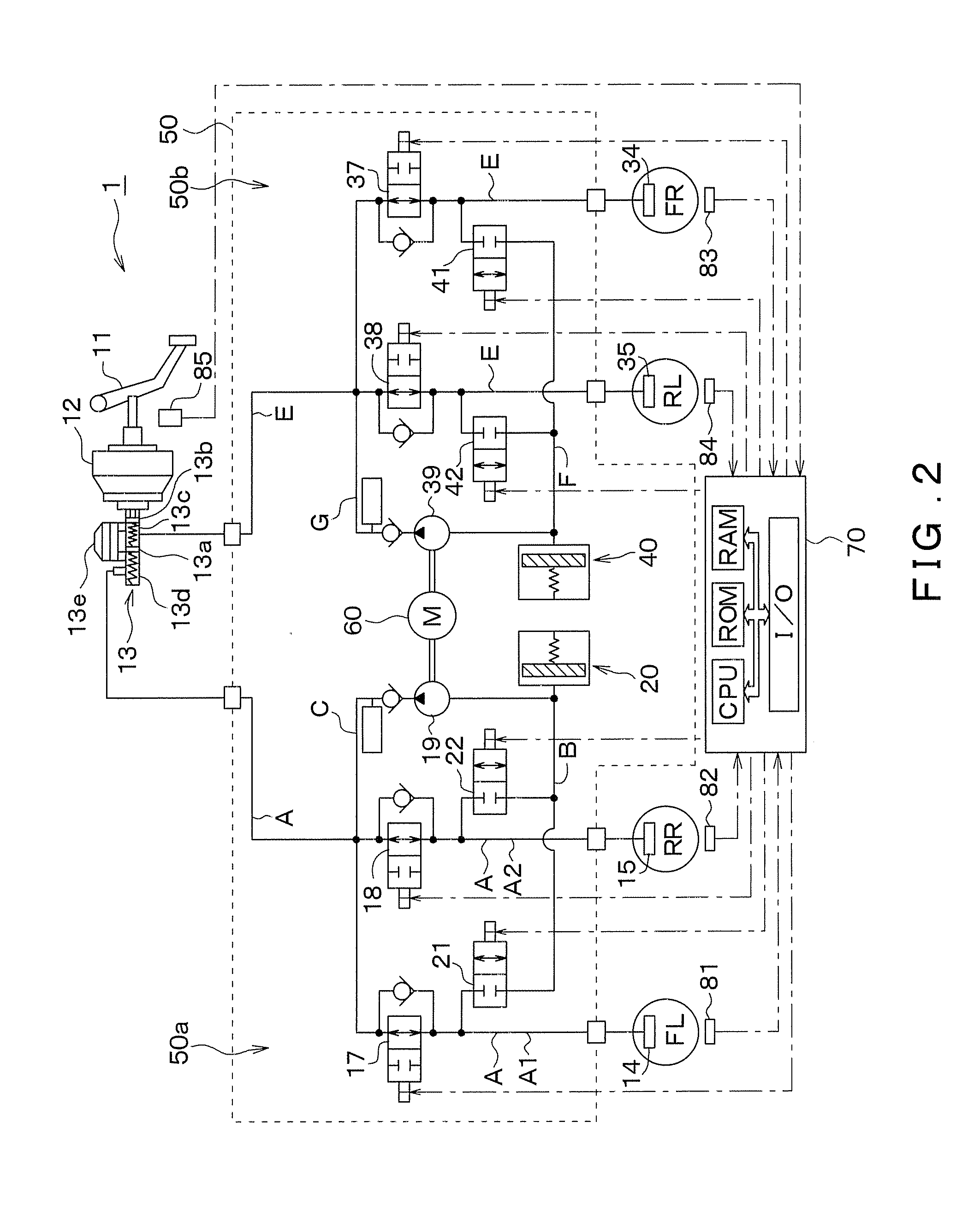
[0040]First, the brake control device 1 of the present invention is described. As shown in FIG. 1, the brake control device 1 includes a brake pedal 11, a servo unit 12, a master cylinder 13 (hereinafter referred to as M / C 13), W / Cs 14, 15, 34, 35, and an actuator 50 for controlling brake fluid pressure. The brake control device 1 also includes a brake ECU 70. The brake ECU 70 operates as a part of various control means to control braking forces generated by the brake control device 1. More specifically, the brake control device 1 includes wheel speed sensors 81 to 84 for outputting a detection signal which is a pulse signal varying based on the spee...


PUM


Abstract

An anti-skid control device or an automatic brake control device gradually increases a W / C pressure for a boost control valve for a front wheel FR or FL on a high-μ surface, by repeating a cycle in which the differential pressure for the boost control valve at the high-μ surface side is kept at the first differential pressure for a first period, and after that kept at the second differential pressure for a second period. Therefore, it is possible to suppress the individual variation in the capability for W / C pressure boosting, and accordingly to suppress the difference of the W / C pressures between the right front wheel and the left front wheel. Thus, it is possible to suppress the yaw torque applied to the vehicle and therefore to suppress the spin of the vehicle.

Description

CROSS REFERENCE TO RELATED APPLICATION[0001]This application is based on and incorporates herein by reference Japanese patent applications No. 2007-266457 filed on Oct. 12, 2007 and No. 2008-204101 filed on Aug. 7, 2008.FIELD OF THE INVENTION[0002]The present invention relates to an ABS control device for a vehicle which performs an anti-skid control (hereinafter referred to as an ABS control) for preventing wheels of the vehicle from locking while braking. The present invention also relates to an automatic brake control device for automatically applying brake fluid pressure to a wheel cylinder (hereinafter referred to W / C). This operation is performed in controls such as anti-side slip control, an active cruise control, and a traction control.BACKGROUND OF THE INVENTION[0003]In Japanese Patent Application Publication No. JP-A-H6-107156, a conventional control is disclosed which operates when a vehicle is running on a μ-split surface, in other words, when a friction coefficient (her...

Claims


Application Information

Patent Timeline
IPC IPC(8): B60K28/16
CPCB60T8/1764
Inventor SAWADA, MOTOTSUGUMINEMATSU, TORU
Owner ADVICS CO LTD
Learn More