
Hybrid vehicle

Inactive Publication Date: 2009-04-16
HONDA MOTOR CO LTD
View PDF12 Cites 9 Cited by
  • Summary
  • Abstract
  • Description
  • Claims
  • Application Information

AI Technical Summary

Benefits of technology

[0013]According to the first aspect of the invention, even if, for example, the first pump serving as the source of supply of the working fluid to the relative rotational force generator develops a malfunction, the provision of the supply switcher and the second pump allows the working fluid to be supplied to the engaging / disengaging device from the second pump. This makes it possible to operate the engaging / disengaging device so as to connect the first drive shaft through which the driving force of the internal combustion engine is transmitted and the second drive shaft connected to the wheels, thus allowing the driving force of the internal combustion engine to be transmitted to the wheels through the intermediary of the first drive shaft and the second drive shaft. Further, the aforesaid arrangement allows a required driving force necessary for driving the vehicle to be generated by the internal combustion engine or by making the internal combustion engine and the motor work together so as to implement a traveling condition required of the vehicle. In addition, the second pump is required to be able to simply operate the engaging / disengaging device, so that a smaller pump may be used for the second pump.
[0015]According to the second aspect of the invention, a malfunction of the first pump serving as the source for supplying the working fluid to the relative rotational force generator can be detected by the malfunction detector. Further, if a malfunction of the first pump is detected, the source of supply of the working fluid to the engaging / disengaging device is changed over to the second pump through the intermediary of the supply switcher, thereby enabling the engaging / disengaging device to be actuated by the second pump. This allows the driving force of the internal combustion engine to be transmitted to the wheels. When no malfunction of the first pump is detected, the source of supply of the working fluid is switched to the first pump, allowing the first pump to supply, as necessary, the working fluid for driving the relative rotational force generator and the working fluid for operating the engaging / disengaging device.
[0019]According to the fourth aspect of the invention, if no malfunction of the first pump is detected, then the electromagnetic clutch is disengaged to prevent the second pump from being driven when the internal combustion engine is running, thus permitting a reduction in load loss in the internal combustion engine.
[0021]According to the fifth aspect of the invention, the second pump can be driven using an existing motor for driving an accessory device, thus allowing the construction for driving the second pump to be easily accomplished without the need for an additional element for driving the second pump. As the motor for an accessory device, there is, for example, a motor for the compressor of an air conditioner.
[0023]According to the sixth aspect of the invention, if no malfunction of the first pump is detected, then the electromagnetic clutch is disengaged to prevent the second pump from being driven when the motor for driving an accessory device is running, thus permitting a reduction in load loss in the motor.

Problems solved by technology

However, if a malfunction of the hydraulic pump serving as the supply source of hydraulic oil occurs, then it becomes difficult to change the phase difference between the two rotors in the motor.
This makes it difficult for the driving force of the motor to satisfy required driving force for driving the vehicle.
Further, a response failure or the like will occur in the engaging / disengaging operation of the engaging / disengaging means, possibly causing a transmission failure when the engaging / disengaging device is engaged to transmit the driving force of the internal combustion engine to wheels.

Method used


Image

  • Hybrid vehicle
  • Hybrid vehicle
  • Hybrid vehicle

Examples


first embodiment

[0034]A first embodiment of the present invention will be described with reference to FIG. 1 to FIG. 6.

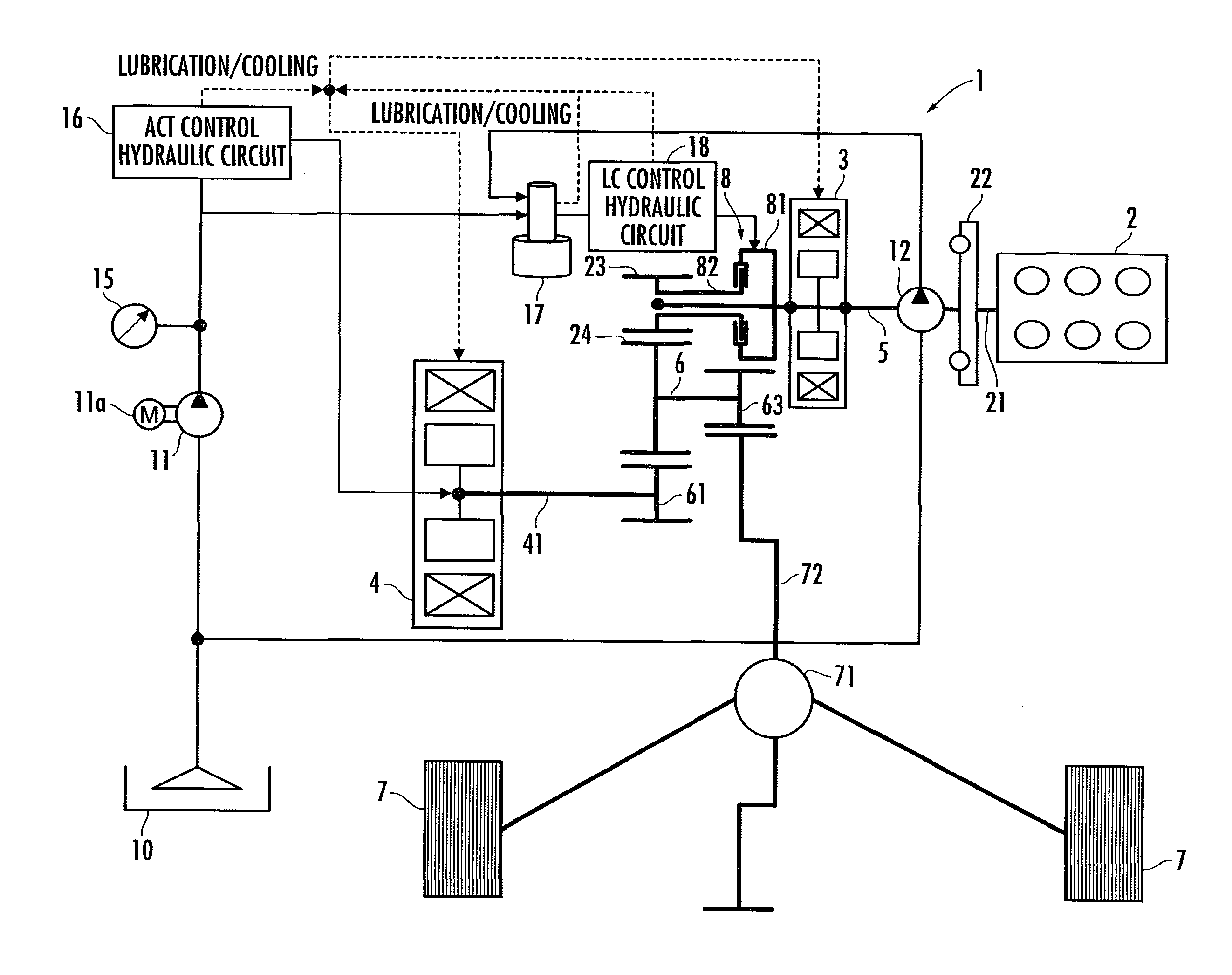
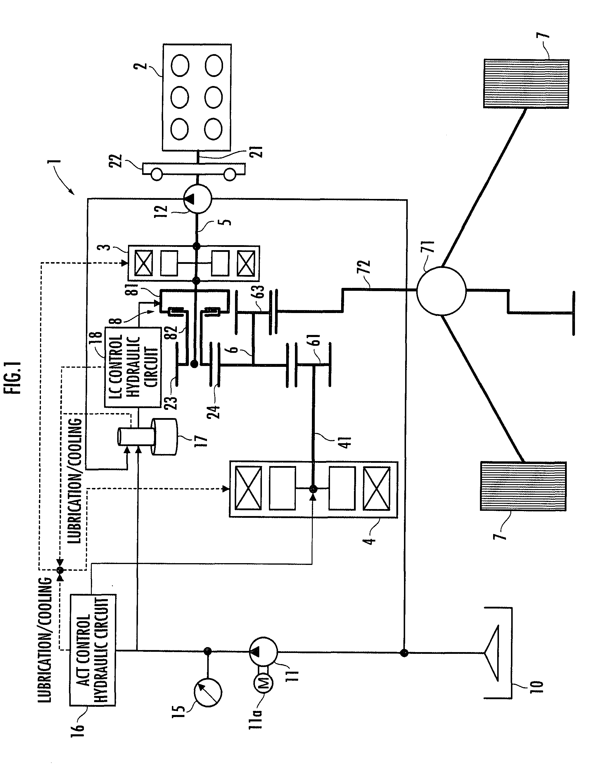
[0035]First, referring to FIG. 1, a hybrid vehicle will be schematically described. FIG. 1 is a block diagram illustrating a drive train for driving a hybrid vehicle according to the present embodiment. A hybrid vehicle 1 has an engine 2, which is an internal combustion engine, a generator 3, and a motor 4. The generator 3 has a rotor thereof connected to a first drive shaft 5 through which a driving force of the engine 2 is transmitted. The driving force of the engine 2 is transmitted to the rotor of the generator 3 through the intermediary of the first drive shaft 5. The generator 3 carries out power generation by the driving force of the engine 2 transmitted to the first drive shaft 5. The electric power generated by the generator 3 is charged in a battery 9 (shown in FIG. 5), which is a power source of the motor 4, and the electric power is supplied from the battery 9 to the mo...

second embodiment

[0132]A second embodiment of the present invention will now be described with reference to FIG. 7 and FIG. 8. The present embodiment differs from the first embodiment only in the construction related to a second pump 12, so that the same constituent elements as those of the first embodiment will be assigned the same reference numerals as those of the first embodiment and the description thereof will be omitted.

[0133]FIG. 7 is a block diagram of a driving system which drives a hybrid vehicle in the present embodiment. Referring to the figure, the description will be focused mainly on aspects that are different from the hybrid vehicle of the first embodiment. In a hybrid vehicle 1 of the present embodiment, the second pump 12 is connected to a third drive shaft 26, which is provided to be interlocked with a first drive shaft 5, through the intermediary of an electromagnetic clutch 13a.

[0134]More specifically, a first pulley 23 secured to an output shaft 21 is provided at one end of t...

third embodiment

[0144]Referring now to FIG. 9 and FIG. 10, a third embodiment of the present invention will be described. The present embodiment differs from the first embodiment only in the construction related to a second pump 12, so that the same constituent elements as those of the first embodiment will be assigned the same reference numerals as those of the first embodiment and the description thereof will be omitted.

[0145]FIG. 9 is a block diagram of a driving system which drives a hybrid vehicle in the present embodiment. Referring to the figure, the description will be focused mainly on aspects that are different from the hybrid vehicle of the first embodiment. In a hybrid vehicle 1 of the present embodiment, the second pump 12 is connected to an output shaft 14b of a motor 14a for driving an accessory device through the intermediary of a first electromagnetic clutch 13b.

[0146]More specifically, the hybrid vehicle 1 in the present embodiment is equipped with the motor 14a for driving an ac...


PUM


Abstract

A hybrid vehicle implements a required traveling condition by generating a required driving force necessary to drive the vehicle even in the case where a supply source of a working fluid develops a malfunction. The hybrid vehicle is equipped with a motor which changes the phase difference between two rotors and an engaging / disengaging device which turns on / off the supply of a driving force of an internal combustion engine, the motor and the engaging / disengaging device being driven by a working fluid. The hybrid vehicle further includes a clutch which carries out the engagement / disengagement between a first drive shaft through which a driving force of an engine is transmitted and a second drive shaft through which a driving force of the motor is transmitted to wheels, an electrically-operated first pump capable of supplying hydraulic oil to a relative rotational force generator of the motor and the clutch, a mechanical second pump which is driven by the engine and which is capable of supplying the hydraulic oil to the clutch, and a solenoid selector valve for selectively switching the source of supply of the hydraulic oil to the clutch to the first pump or the second pump.

Description

BACKGROUND OF THE INVENTION[0001]1. Field of the Invention[0002]The present invention relates to a hybrid vehicle equipped with an internal combustion engine, a generator, and a motor.[0003]2. Description of the Related Art[0004]Hitherto, as this type of hybrid vehicle, there has been known a hybrid vehicle equipped with an internal combustion engine, a generator connected to a drive shaft of the internal combustion engine, a motor, and an output shaft which is connected to the drive shaft of the motor and which also permits connection to the drive shaft of the internal combustion engine through the intermediary of an engaging / disengaging device, wheels being connected to the output shaft, as disclosed in the publication of Japanese Patent No. 3183062 (hereinafter referred to as patent document 1).[0005]The hybrid vehicle is capable of traveling in a travel mode which uses the driving force of the motor by engagement / disengagement performed by the engaging / disengaging device accordi...

Claims


Application Information

Patent Timeline
IPC IPC(8): H02K16/02B60L50/16
CPCB60K1/02Y02T10/6239B60K6/365B60K6/387B60K6/442B60K6/445B60L11/123B60L2240/423B60W10/02B60W10/06B60W10/08B60W10/30B60W20/00B60W2520/10B60W2540/10B60W2540/12B60W2710/0666B60W2710/083Y02T10/6217Y02T10/6234Y02T10/6286Y02T10/642Y02T10/7077B60K6/26B60L50/61Y02T10/62Y02T10/64Y02T10/70B60W2050/146B60W20/15B60W50/0205Y02T10/7072
Inventor TSUTSUMI, DAISUKEISEGAWA, HIROYUKIISOGAI, YUTAKATANAKA, MASASHIFUJISHIRO, NAOKI
Owner HONDA MOTOR CO LTD
Learn More