Charging Device, Electric Vehicle Equipped With the Charging Device and Charging Control Method

a charging device and electric vehicle technology, applied in hybrid vehicles, electric devices, propulsion by batteries/cells, etc., can solve the problems of insufficient environmental protection, large amount of carbon dioxide generated, and limited output of electric motors, and achieve the effect of reducing the energy cost of electric vehicles 40

Active Publication Date: 2009-04-16
TOYOTA JIDOSHA KK
View PDF5 Cites 78 Cited by
  • Summary
  • Abstract
  • Description
  • Claims
  • Application Information

AI Technical Summary

Benefits of technology

[0110]As in the above, according to the third embodiment, not only the emission amount of carbon dioxide but also the cost of commercial electric power at the time of charging (generally, the late-night electric power is less expensive than the daytime electric power) is taken into consideration. Therefore, besides contribution to environmental protection, reduction of the energy cost of the electric vehicle 40 can be achieved.
[0111]In a fourth embodiment, the CO2 emission amount associated with the running of the motor vehicle is calculated, and the calculated CO2 emission amount is output to an external device or the like outside the motor vehicle via a charging cable, at the time of charging from a charging station 30. Due to this, the data of the CO2 emission amount associated with the running of the motor vehicle becomes available at a server outside the motor vehicle, or a terminal device 70 (a personal computer or the like) at one's home, and therefore the management of the CO2 emission amount and the comparison with other people (vehicles) become possible.

Problems solved by technology

In this hybrid vehicle, if the vehicle travels for a long time without external charging, the output of the electric motor is restricted.
However, in the generation of commercial electric power, a large amount of carbon dioxide is generated in the fire power generation in which electric power is generated by burning petroleum, a gas, etc.
Therefore, in an electric vehicle equipped with an external charging function that is capable of charging the battery from a commercial electric power source, if merely the amount of charging from the commercial electric power source is increased, there is a possibility of insufficient contribution to environmental protection.

Method used


Image

  • Charging Device, Electric Vehicle Equipped With the Charging Device and Charging Control Method
  • Charging Device, Electric Vehicle Equipped With the Charging Device and Charging Control Method
  • Charging Device, Electric Vehicle Equipped With the Charging Device and Charging Control Method

Examples


first embodiment

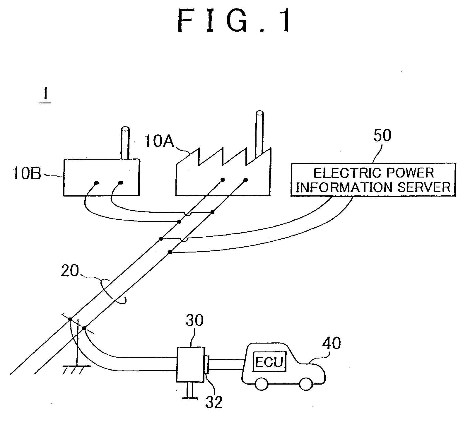
[0055]FIG. 1 is a schematic diagram of an electric power system that includes an electric vehicle according to this invention. Referring to FIG. 1, an electric power system 1 includes power plants 10A, 10B, an electricity transmission line 20, a charging station 30, an electric vehicle 40, and an electric power information server 50.

[0056]The power plants 10A, 10B generate commercial electric power, and supply the generated commercial electric power to the electricity transmission line 20. Incidentally, other power plants (not shown) are also connected to the electricity transmission line 20. Such power plants include, for example, fire power plants that generate electric power by burning petroleum, a gas, etc., atomic power plants, hydraulic power plants, etc. The charging station 30 is connected to the electricity transmission line 20. The charging station 30 is a facility for charging the electric vehicle 40 with commercial electric power supplied from the electricity transmissio...

second embodiment

[0096]In a second embodiment, the CO2 emission amount received from the electric power information server 50 at each time of charging from the charging station 30 is added up to calculate the total emission amount of carbon dioxide. Therefore, from the viewpoint of the total emission amount of carbon dioxide, the degree of contribution of the electric vehicle to the environment can be evaluated. Furthermore, by presenting the total emission amount of carbon dioxide to users, the users can be made conscious of environmental protection.

[0097]FIG. 8 is an overall block diagram of an electric vehicle according to the second embodiment of the invention. Referring to FIG. 8, an electric vehicle 40A has a construction similar to the construction of the electric vehicle 40 according to the first embodiment, but further includes a storage portion 144, and includes an HV-ECU 140A instead of the HV-ECU 140.

[0098]The storage portion 144 is a re-writable non-volatile memory. The storage portion ...

third embodiment

[0104]In a third embodiment, information regarding the cost of commercial electric power is further included in the electric power information, and the cost of commercial electric power is taken into consideration in judgment as to whether or not to execute the charging from the charging station 30.

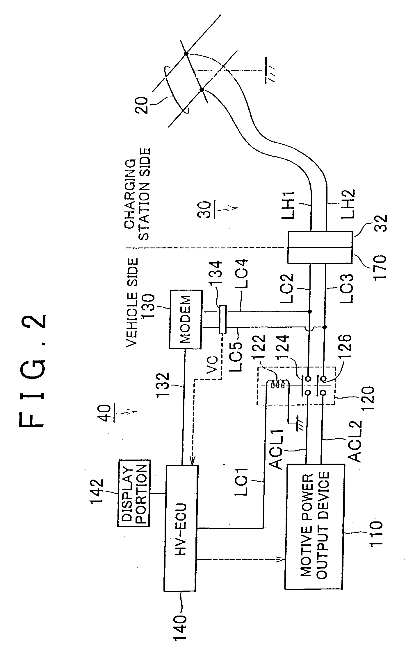
[0105]The overall construction of an electric vehicle according to the third embodiment is the same as that of the electric vehicle 40 according to the first embodiment shown in FIG. 2.

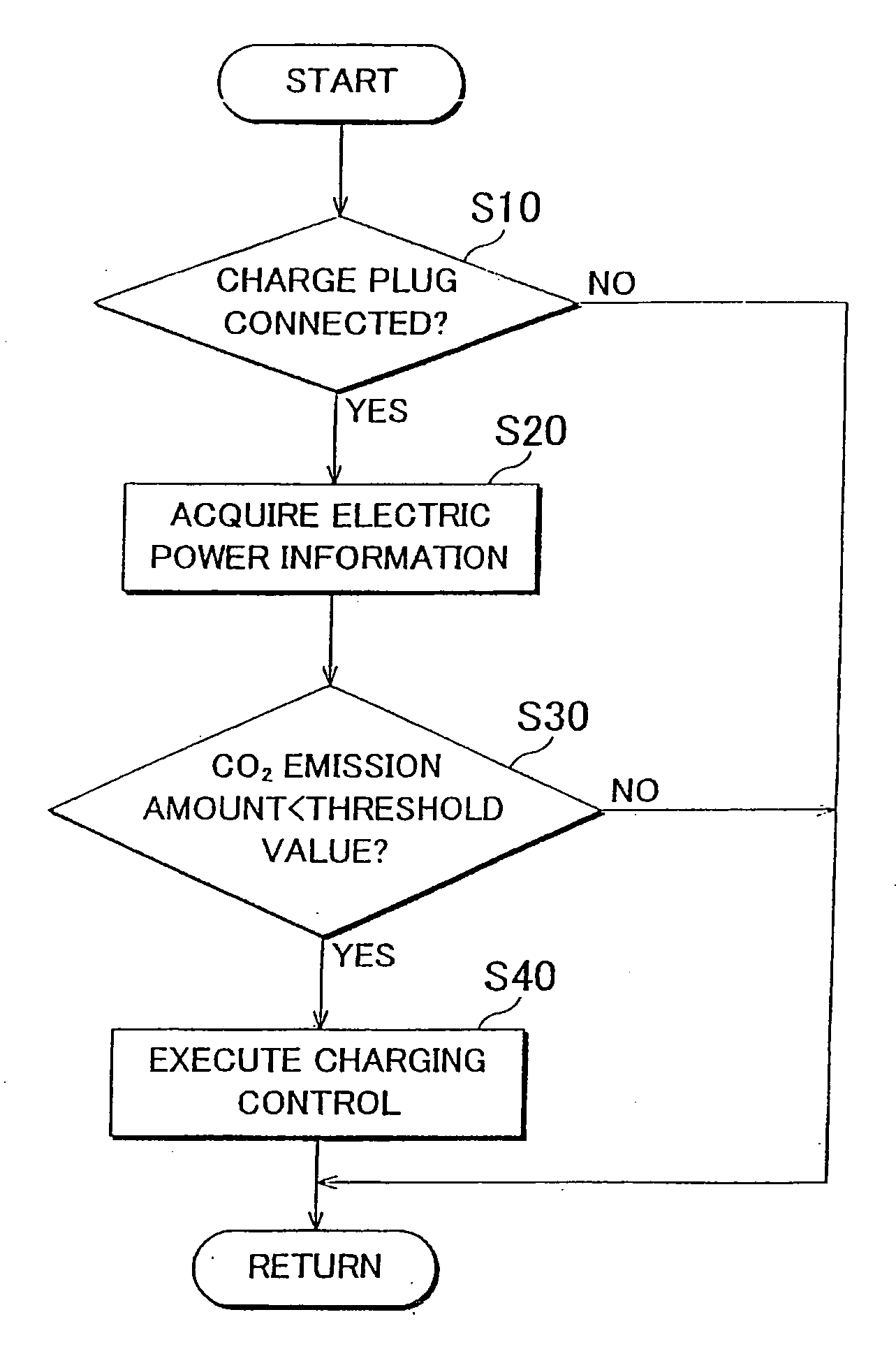
[0106]FIG. 10 is a flowchart of a process regarding judgment as to whether or not to execute the charging control by the HV-ECU 140 according to the third embodiment. Incidentally, the process shown in this flowchart is called up from a main routine and is executed every certain time or every time a predetermined condition holds.

[0107]Referring to FIG. 10, the process shown in this flowchart further includes step S35 in addition to the process shown in FIG. 3. Specifically, if in step S30 it is determined t...


PUM


Abstract

An HV-ECU acquires electric power information from an electricity transmission line by using a modem. The electric power information includes information regarding the amount of carbon dioxide having been emitted in the generating process of the commercial electric power supplied from an electricity transmission line. When the CO2 emission amount is below a pre-set CO2 emission amount, the HV-ECU inputs the commercial electric power, and outputs a command to charge an electricity storage device to a motive power output device, so that the motive power output device executes a charging control of the electricity storage device.

Description

FIELD OF THE INVENTION[0001]The invention relates to a charging device, a mobile object equipped with the charging device, an electric vehicle equipped with the charging device, a charging control method, and a charging control method of an electric vehicle. More particularly, the invention relates to a charging device charged from a commercial electric power source, a mobile object equipped with the charging device, an electric vehicle equipped with the charging device, a charging control method, and a charging control method or an electric vehicle.BACKGROUND OF THE INVENTION[0002]In recent years, electric vehicles, hybrid vehicles, etc. in which an electricity storage device, such as a battery, a capacitor, etc., and an inverter, and a motor driven by the inverter are mounted as motive power sources, are drawing attention as environment-friendly motor vehicles.[0003]A hybrid vehicle equipped with an external charging function of charging the battery through the use of an external ...

Claims


Application Information

Patent Timeline
Patent Type & Authority Applications(United States)
IPC IPC(8): H02J7/00B60L50/16
CPCB60K1/02Y02T10/6239B60K6/445B60L11/123B60L11/14B60L11/1812B60L11/1814B60L11/1816B60L11/1824B60L11/184B60L11/1846B60L11/1848B60L15/007B60L2220/54B60L2230/16B60L2240/62B60W10/06B60W10/08B60W10/26B60W20/00B60W2510/244B60W2550/402H02J7/042Y02T10/6217Y02T10/6269Y02T10/6286Y02T10/641Y02T10/7005Y02T10/7077Y02T10/7088Y02T10/7291Y02T90/121Y02T90/127Y02T90/128Y02T90/14Y02T90/16Y02T90/162Y02T90/163Y02T90/169Y04S30/14B60K6/365B60L53/14B60L53/22B60L50/61B60L50/16B60L53/24B60L53/30B60L53/64B60L53/65B60L53/665B60L53/305B60W2556/50H02J7/007Y02T10/62Y02T10/64Y02T10/7072Y02T10/72Y02T10/70Y02T90/12Y02T90/167B60W2050/146H02J7/04B60W10/28B60W10/24B60W20/15
Inventor TONEGAWA, HIROMIICHISHI, MASATOOYOBE, HICHIROSAINAKAMURA, MAKOTOISHIKAWA, TETSUHIROFUJITAKE, YOSHINORI
Owner TOYOTA JIDOSHA KK
Why Eureka
Try Eureka