Base station antenna with beam shaping structures

Inactive Publication Date: 2009-04-16
AMPHENOL CORP
View PDF9 Cites 35 Cited by
  • Summary
  • Abstract
  • Description
  • Claims
  • Application Information

AI Technical Summary

Benefits of technology

[0009]The present invention meets the needs described above in dual polarization base station antennas that produce beams in which the 3 dB azimuth beamwidth of the vertical polarization component E(theta) is within 5° of the 3 dB azimuth beamwidth of the horizontal polarization E(phi). The antenna also maintains E(theta) and E(phi) within 3 dB of each other over a wide azimuth beamwidth up to 120°, and over a wide bandwidth up to 30% of the center frequency. The antenna achieves these performance characteristics through the use of beam shapi

Problems solved by technology

The system performance is generally limited by the cross-correlation coefficient between the two spatially diversified antennas.
In actual communication systems, signals encounter multi-path propagation and multiple reflections, which cause depolarization of the signal.
In reality, prior art base station antennas are not able to maintain E(theta) and E(phi) within 3 dB of each other over an azimuth range equal to 120° sector coverage.
Again, in reality, prior art base station antennas are not able to maintain E(theta) and E(phi) within 3 dB of each other over a 30% bandwidth as well as over a 120° azimuth range.
As a result, the communication performance drops near the edge of the cell, potentially causing more dr

Method used


Image

  • Base station antenna with beam shaping structures
  • Base station antenna with beam shaping structures
  • Base station antenna with beam shaping structures

Examples


Embodiment Construction

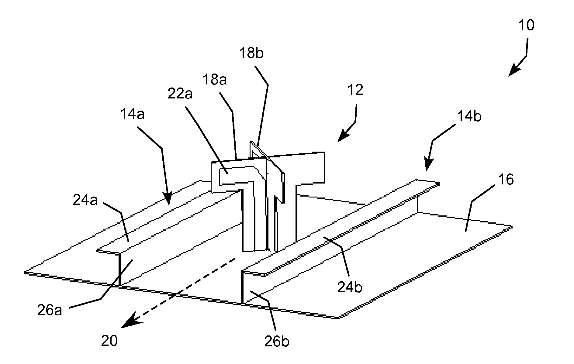
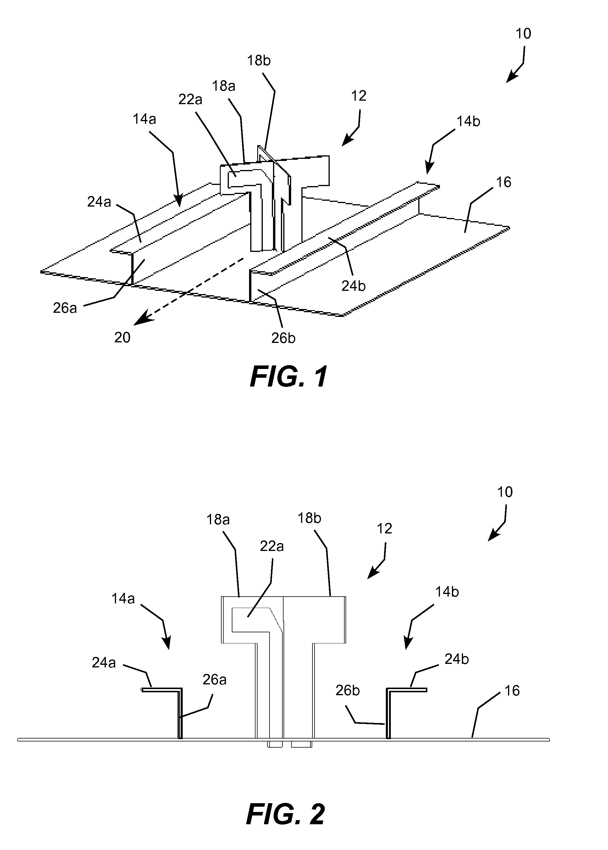
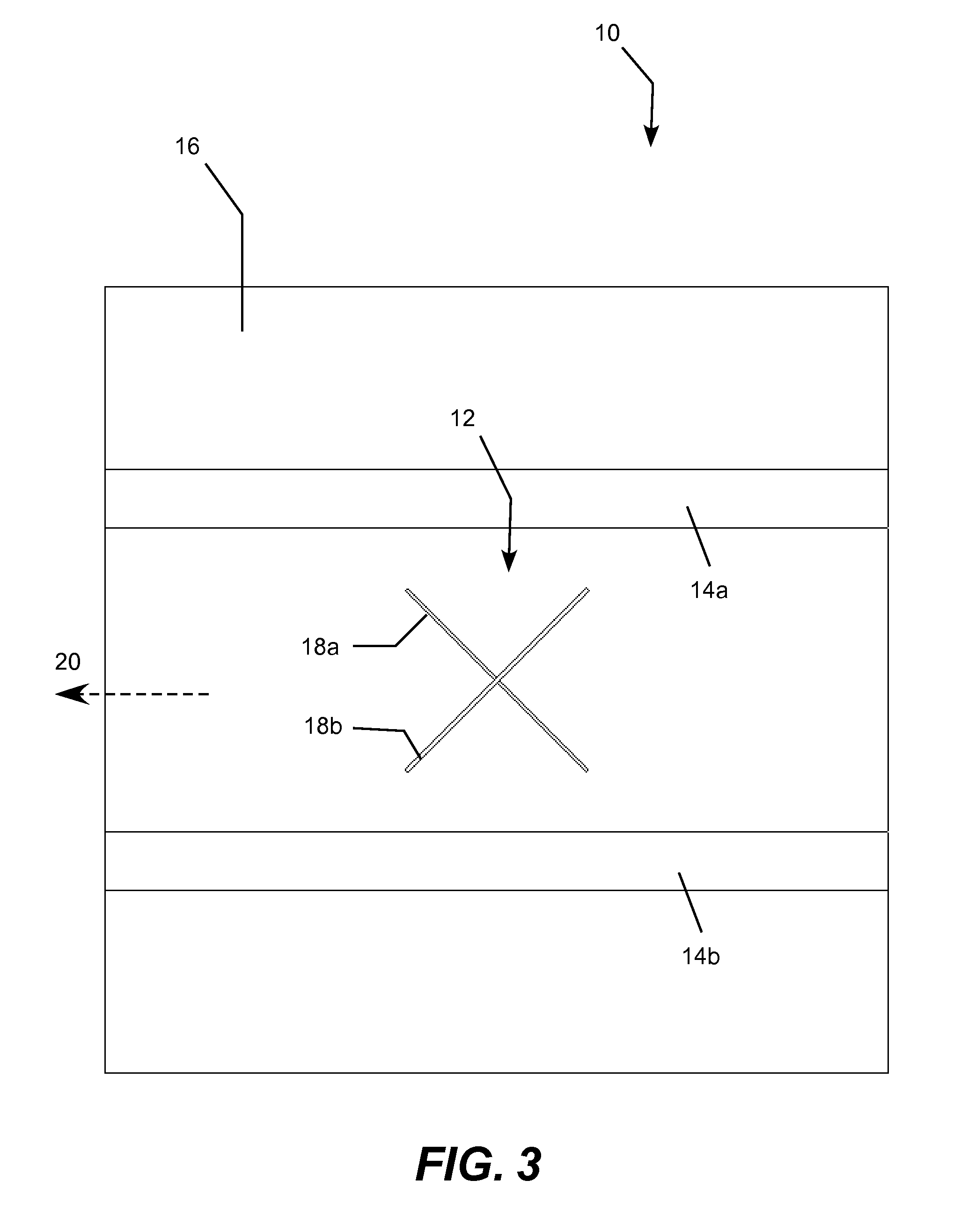
[0038]The present invention may be embodied in a wide range of dual polarization antennas with one or more arrays of dipole antenna elements and one or more beam shaping structures designed to confer desired vertical polarization E(theta) and horizontal polarization E(phi) beamwidth and bandwidth characteristics. For example, the invention may be embodied in a single-band antenna elements with one array of dipole antennas and one arrangement of beam shaping structures, a dual-band antenna with two arrays of dipole antenna elements and two arrangements of beam shaping structures, a triple-band antennas with three arrays of dipole antenna elements and three arrangements of beam shaping structures, and so forth. The beam shaping structures are typically implemented as a pair of inverted-L shaped flange sections connected to the ground plane running the length of the associated array with one beam shaping channel located on each side of the antenna array. The flange sections may be elec...


PUM


Abstract

A dual polarization base station antenna producing a beam having 3 dB azimuth beamwidth of E(theta) within 5° of the 3 dB azimuth beamwidth of E(phi). The antenna also maintains E(theta) and E(phi) within 3 dB of each other over a wide beamwidth up to 120°, and over a wide bandwidth of 30% of the center frequency. The antenna achieves these performance characteristics through beam shaping structures connected to or located near the ground plane supporting the dipole antenna elements. By adjusting the locations and shapes of the beam shaping structures, specific antennas are designed to meet these design characteristics for different desired beamwidths, including 45°, 60°, 90° and 120°.

Description

REFERENCE TO RELATED APPLICATION[0001]This application claims filing priority to commonly owned U.S. Provisional Patent Application Ser. No. 60 / 979,874, entitled “Dual Polarized Array Antenna” filed Oct. 15, 2007, which is incorporated herein by reference.TECHNICAL FIELD[0002]The present invention pertains to the field of telecommunication antennas and, more particularly, to a base station antenna for a wireless telecommunication system that includes beam shaping structures that control the shape of the beam emitted by the antenna.BACKGROUND[0003]Diversity techniques are widely used in wireless communications to improve the signal performance. Spatial diversity typically uses two or more antennas spatially separated. The system performance is generally limited by the cross-correlation coefficient between the two spatially diversified antennas. The optimum performance occurs only when the cross-correlation coefficient approaches zero.[0004]Polarization diversity provides an alternati...

Claims


Application Information

Patent Timeline
IPC IPC(8): H01Q21/26H01Q5/10
CPCH01Q21/26H01Q1/246
Inventor CHAIR, RICKY
Owner AMPHENOL CORP
Why Eureka
Try Eureka