
X-ray ct apparatus and method for processing x-ray projection data

Active Publication Date: 2009-04-16
GE MEDICAL SYST GLOBAL TECH CO LLC
View PDF23 Cites 44 Cited by
  • Summary
  • Abstract
  • Description
  • Claims
  • Application Information

AI Technical Summary

Benefits of technology

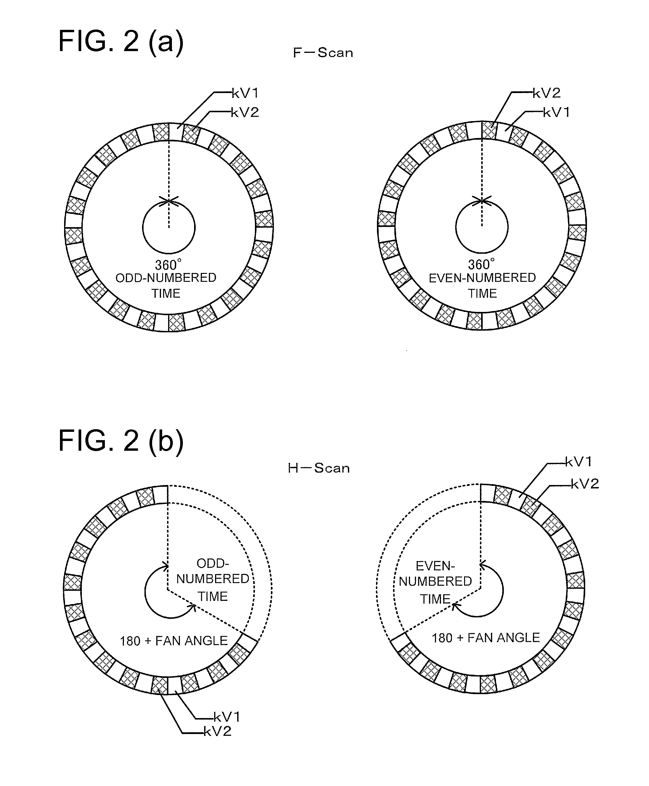
[0004]Therefore, an X-ray CT apparatus for switching X-ray tube voltages at high speed every view or plural views has been considered to reduce the miss registration artifact upon the dual energy scan at the X-ray CT apparatus comprising one X-ray tube and one multi-row X-ray detector. In the X-ray CT apparatus, however, the proportion of an X-ray tube voltage (hereinafter defined as transient tube voltage) in a transient state developed while the X-ray tube voltage is shifted from a low X-ray tube voltage to a high X-ray tube voltage, increases as the X-ray tube voltage is changed at high speed. Therefore, the number of X-ray projection data unused in image reconstruction, corresponding to the transient tube voltage increases and thereby the efficiency of utilization of X-rays is degraded, thus leading to increases in image-quality degradation and needless exposure.
[0005]Therefore, it is an object of the present invention to realize a reduction in exposure and an improvement in image quality by improving X-ray utilization efficiency upon dual energy scanning every view or plural views.
[0021]According to the X-ray CT apparatus of the present invention, an advantage is brought about in that an X-ray CT apparatus can be realized wherein a conversion process for converting the transient energy projection data to different data is conducted upon scanning or imaging for switching X-ray tube voltages every at least one view, and at least the data subsequent to the conversion process are used in image reconstruction, whereby exposure is reduced and image quality is further improved.

Problems solved by technology

Therefore, the number of X-ray projection data unused in image reconstruction, corresponding to the transient tube voltage increases and thereby the efficiency of utilization of X-rays is degraded, thus leading to increases in image-quality degradation and needless exposure.

Method used


Image

  • X-ray ct apparatus and method for processing x-ray projection data
  • X-ray ct apparatus and method for processing x-ray projection data
  • X-ray ct apparatus and method for processing x-ray projection data

Examples


Embodiment Construction

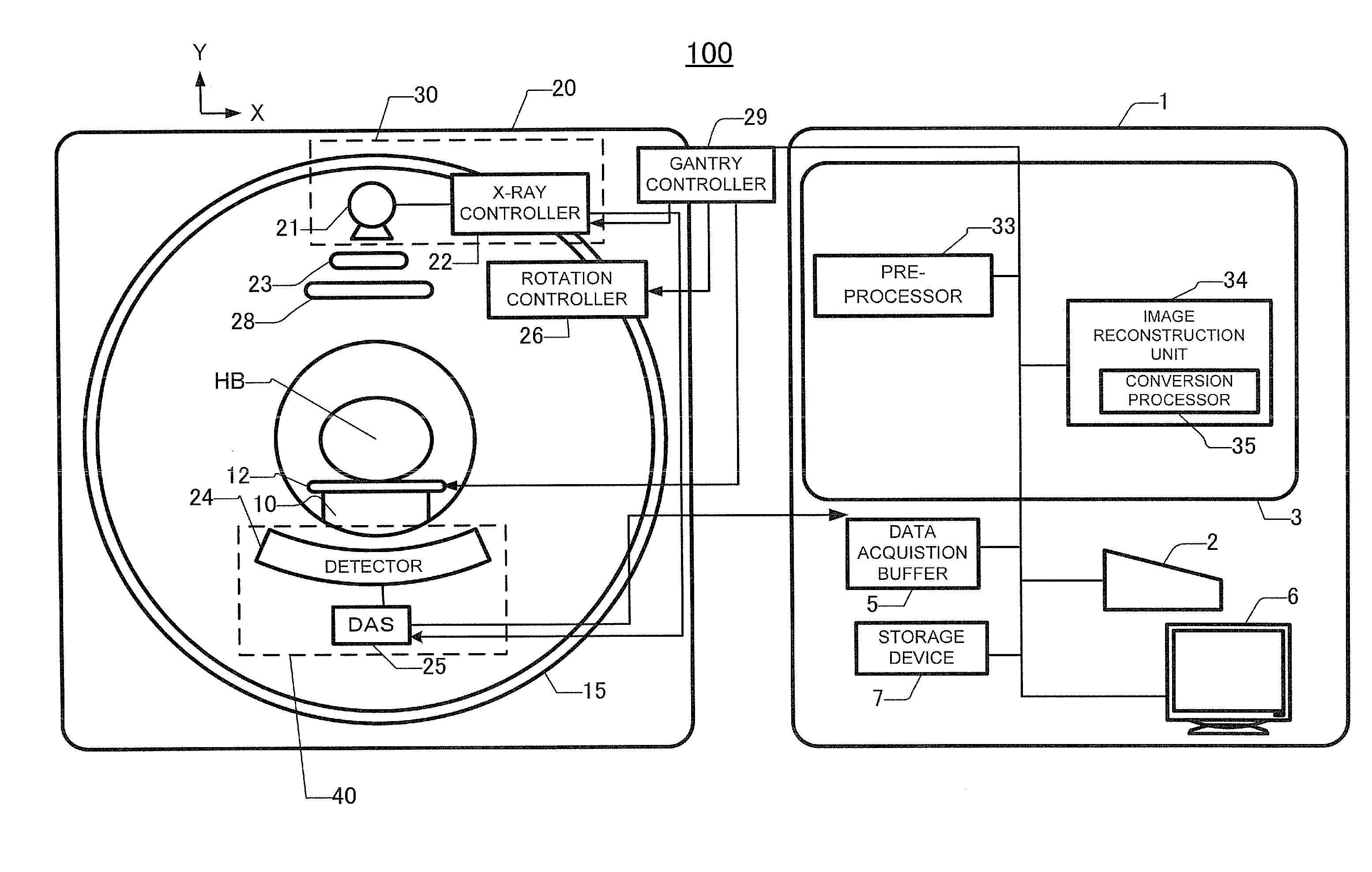
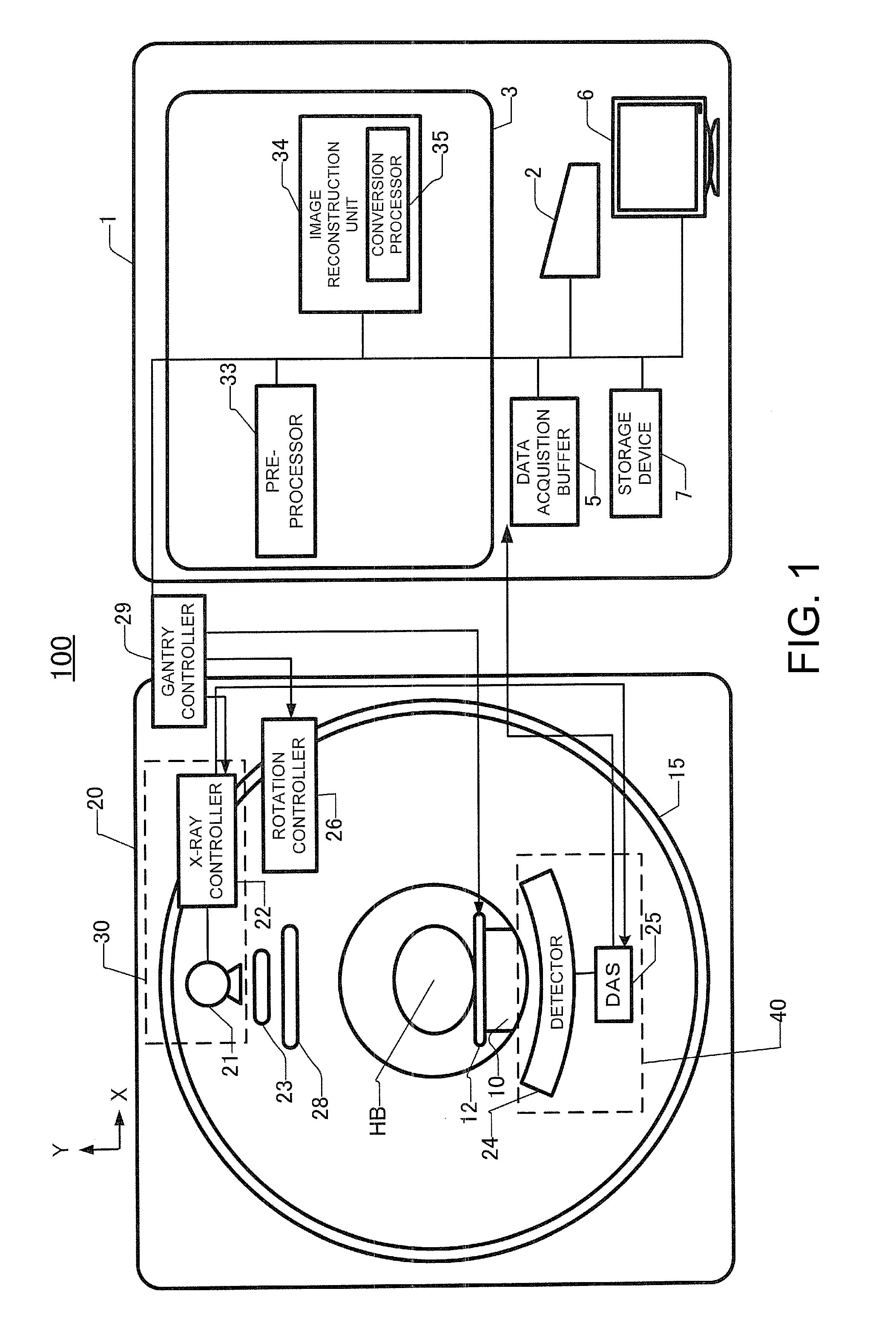
[0038]FIG. 1 is a configuration block diagram showing an X-ray CT apparatus 100 according to an embodiment of the present invention. The X-ray CT apparatus 100 is equipped with an operation console 1, an imaging or photographing table 10 and a scan gantry 20.

[0039]The operation console 1 includes an input device 2 such as a keyboard or mouse or the like, which accepts an input from an operator, a central processing unit 3 which executes a pre-process, an image reconstructing process, a post-process, etc., and a data acquisition buffer 5 which acquires or collects X-ray detector data acquired by the scan gantry 20. Further, the operation console 1 includes a monitor 6 which displays a tomographic image image-reconstructed from projection data obtained by pre-processing the X-ray detector data, and a storage device 7 which stores programs, X-ray detector data, projection data and X-ray tomographic images therein. An input for imaging or photographing conditions is inputted from the in...


PUM


Abstract

An X-ray CT apparatus includes an X-ray irradiation unit for applying X-rays based on a first X-ray tube voltage and X-rays based on a second X-ray tube voltage to a subject by being switched every one view, a projection data acquisition unit for acquiring projection data by which X-ray tube voltage information about the applied X-rays are identified, and an image reconstruction unit for identifying first energy projection data based on the first X-ray tube voltage, second energy projection data based on the second X-ray tube voltage, and transient energy projection data acquired upon switching between the first and second X-ray tube voltages based on the X-ray tube voltage information, the image reconstruction unit including a conversion processor that converts the transient energy projection data to another data using the transient energy projection data and performs image reconstruction using the data subsequent to the conversion process.

Description

CROSS REFERENCE TO RELATED APPLICATIONS[0001]This application claims the benefit of Japanese Patent Application No. 2007-267679 filed Oct. 15, 2008, which is hereby incorporated by reference in its entirety.BACKGROUND OF THE INVENTION[0002]The subject matter disclosed herein relates to a dual energy scan technique suitable for use in an X-ray CT apparatus.[0003]A technique for a dual energy scan at an X-ray CT apparatus comprising one X-ray tube and one multi-row X-ray detector has been disclosed in, for example, Japanese Unexamined Patent Publication No. 2003-37778. In the dual energy scan at such a conventional X-ray CT apparatus, imaging or scanning was first conducted at a low X-ray tube voltage and the X-ray tube voltage was then raised to perform scanning at the high X-ray tube voltage. According to the present method, a time difference for raising the X-ray tube voltage has occurred between the scans. It is therefore considered that a miss registration artifact occurs due to ...

Claims


Application Information

Patent Timeline
IPC IPC(8): A61B6/00
CPCA61B6/032A61B6/037A61B6/405G06T2211/408A61B6/541G06T11/006A61B6/482
Inventor NISHIDE, AKIHIKOGOHNO, MAKOTO
Owner GE MEDICAL SYST GLOBAL TECH CO LLC
Learn More