Scroll compressor with scroll deflection compensation

a compressor and scroll technology, applied in the direction of machines/engines, rotary/oscillating piston pump components, liquid fuel engines, etc., can solve the problems of thermal expansion of the wrap of both affecting the ability to maintain sealing between the scroll members, and axial deformation of the base plate of the fixed and orbiting scroll members, etc., to achieve the effect of improving efficiency

Active Publication Date: 2009-04-16
EMERSON CLIMATE TECH INC
View PDF31 Cites 13 Cited by
  • Summary
  • Abstract
  • Description
  • Claims
  • Application Information

AI Technical Summary

Benefits of technology

[0004]A scroll compressor can compress a fluid from a suction pressure to a discharge pressure greater than the suction pressure. The scroll compressor can use a non-orbiting scroll member and an orbiting scroll member, each having wraps positioned in meshing engagement with one another. The relative

Problems solved by technology

During operation, however, the base plates of the fixed and orbiting scroll members can experience axial deformations due to high fluid pressure present in the compression chambers formed by the intermeshing wraps.
Additionally, the wraps of both the fixed

Method used


Image

  • Scroll compressor with scroll deflection compensation
  • Scroll compressor with scroll deflection compensation
  • Scroll compressor with scroll deflection compensation

Examples


Embodiment Construction

[0013]The following description is merely exemplary in nature and is not intended to limit the present disclosure, application, or uses.

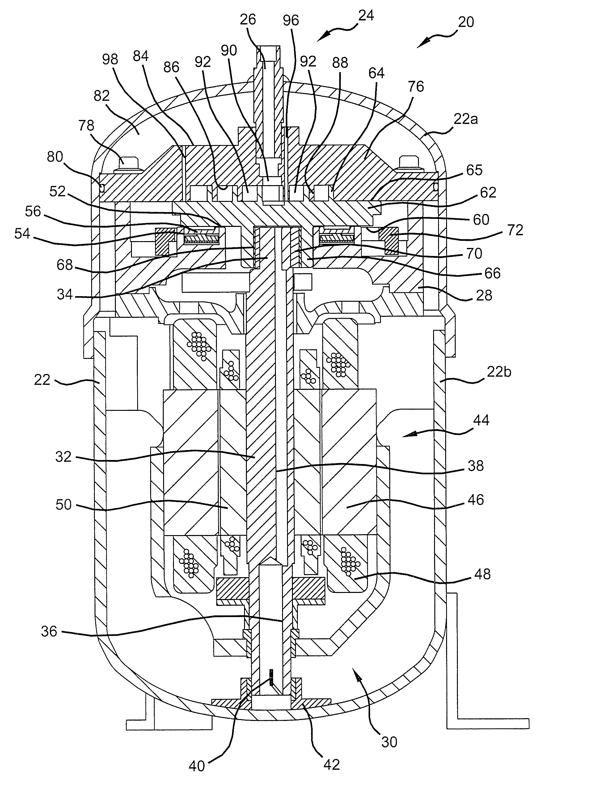
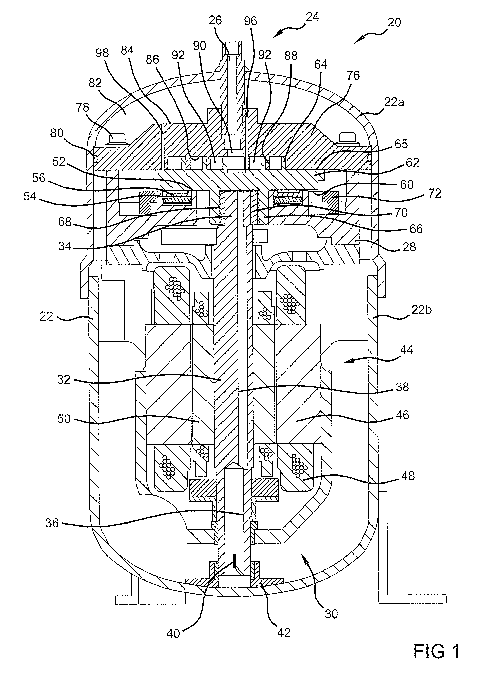
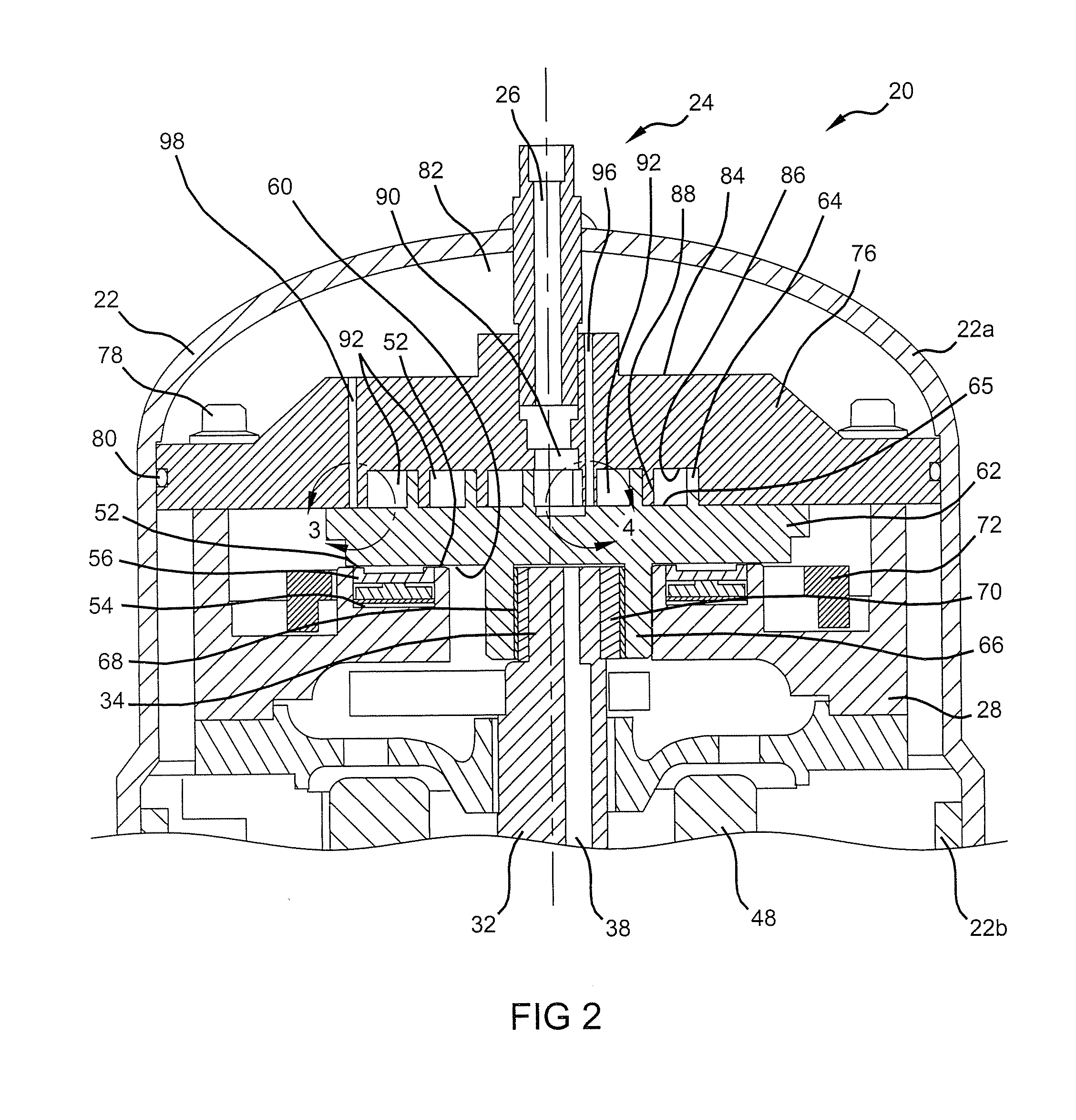
[0014]Referring to FIGS. 1 and 2, an exemplary scroll compressor 20 according to the present teachings is shown. Compressor 20 comprises a shell 22 having an upper portion 22a that is attached to a lower portion 22b in a sealed relationship. Shell 22 can be generally cylindrical. Upper shell 22a is provided with a refrigerant discharge port 24 through which a refrigerant discharge passage 26 extends. A stationary main bearing housing or body 28 and a lower bearing assembly 30 are secured in shell 22. A driveshaft or crankshaft 32 having an eccentric crankpin 34 at the upper end thereof is rotatably journaled in main bearing housing 28 and in lower bearing assembly 30. Crankshaft 32 has at the lower end a relatively large diameter concentric bore 36 which communicates with a radially outwardly inclined small diameter bore 38 extending upwardly theref...


PUM


Abstract

A scroll compressor may incorporate controlled bending of a scroll member to compensate for axial deformations that can occur between the scroll members. The controlled bending may be through the use of fluid pressure in a sealed chamber that communicates with a surface of the scroll member opposite the intermeshing wraps. Fluid passageways can extend through the scroll member between the sealed chamber and the intermeshing wraps. The controlled bending can increase the uniformity of the contact between the scroll members and improve the efficiency of the compressing operation.

Description

CROSS-REFERENCE TO RELATED APPLICATIONS[0001]This application claims the benefit of U.S. Provisional Application No. 60 / 979,543, filed on Oct. 12, 2007. The disclosure of the above application is incorporated herein by reference.FIELD[0002]The present teachings relate generally to scroll compressors and, more particularly, to scroll compressors with scroll deflection compensation.BACKGROUND AND SUMMARY[0003]The statements in this section merely provide background information related to the present teachings and may not constitute prior art.[0004]A scroll compressor can compress a fluid from a suction pressure to a discharge pressure greater than the suction pressure. The scroll compressor can use a non-orbiting scroll member and an orbiting scroll member, each having wraps positioned in meshing engagement with one another. The relative movement between the scroll members causes the fluid pressure to increase as the fluid moves from the suction port to the discharge port. To improve ...

Claims


Application Information

Patent Timeline
IPC IPC(8): F01C1/02F04C18/02F01C21/00F04C29/00
CPCF04C18/0215F04C27/005F04C23/008
Inventor IGNATIEV, KIRILL
Owner EMERSON CLIMATE TECH INC
Why Eureka
Try Eureka