Modulated if receiver and method

a receiver and module technology, applied in the field of radio receivers, can solve the problems of increasing the cost of the receiver chip, increasing the chip area required, and unwanted direct current (dc) signal levels at the output of the mixer, so as to reduce modulation, reduce modulation, and reduce the effect of modulation

Inactive Publication Date: 2009-04-16
SILICON LAB INC
View PDF5 Cites 12 Cited by
  • Summary
  • Abstract
  • Description
  • Claims
  • Application Information

AI Technical Summary

Benefits of technology

[0013]An embodiment of a modulated intermediate frequency receiver with phase compensation includes a low noise amplifier with an input for receiving a radio frequency signal and an output and a modulation source configured to generate a first modulation control signal at a first output and generate a second modulation control signal at a second output. A local oscillator has an input coupled to the first output of the modulation source and is configured to generate a sine phase local oscillator signal at a first output and a cosine phase local oscillator signal at a second output in response to the first modulation control signal from the modulation source. A first mixer has a first input coupled to the first output of the low noise amplifier, a second input coupled to the first output of the local oscillator, and an output. A first DC filter has an input coupled to the output of the first mixer and an output. A first receive filter has an input coupled to the output of the first DC filter and an output. A second mixer has a first input coupled to the output of the low noise amplifier, a second input coupled to the second output of the local oscillator, and an output. A second DC filter has an input coupled to the output of the second mixer and an output. A second receive filter has an input coupled to the output of the second DC filter and an output coupled to the second input of the demodulator. A phase compensation stage has a first input coupled to the output of the first receiver filter, a second input coupled to the output of the second receiver filter, a third input coupled to the second output of the modulation source, and an output. And a discriminator has a first input coupled to the output of the phase compensation stage and configured to generate a received data signal at an output.
[0014]An embodiment of a method for receiving a signal in a modulated intermediate frequency receiver sets forth receiving and amplifying a radio frequency signal to obtain a received radio frequency signal, generating a first modulation control signal, and generating a first modulated local oscillator signal responsive to the first modulation control signal. The method also calls for mixing the received radio frequency signal with the first modulated local oscillator signal to obtain a first modulated intermediate frequency signal. The method further recites DC filtering the first modulated intermediate frequency signal to obtain a first DC filtered modulated intermediate frequency signal. The method further recites receive channel bandwidth filtering the first DC filtered modulated intermediate frequency signal to obtain a first bandwidth filtered receive signal. Finally, the method calls for demodulating the first bandwidth filtered receive signal to obtain a received data signal.
[0015]A refinement of this embodiment of a receive method calls for generating a second modulation control signal related to the first modulation control signal, mixing the second frequency modulation control signal with the first bandwidth filtered receive signal to reduce modulation introduced by the first modulation control signal to obtain a first compensated receive signal, and receive channel bandwidth filtering the first compensated receive signal before demodulating to obtain the received data signal.
[0016]In another refinement of the method, the step of generating a first modulated local oscillator signal involves generating a sine phase and a cosine phase of the first modulated local oscillator signal responsive to the first modulation control signal. The step of mixing the received radio frequency signal with the first modulated local oscillator signal to obtain a first modulated intermediate frequency signal involves mixing the received radio frequency signal with the sine phase of the first modulated local oscillator signal to obtain the first modulated intermediate frequency signal. This refinement also calls for mixing the received radio frequency signal with the cosine phase of the first modulated local oscillator signal to obtain a second modulated intermediate frequency signal, DC filtering the second modulated intermediate frequency signal to obtain a second DC filtered modulated intermediate frequency signal, and receive channel bandwidth filtering the second DC filtered modulated intermediate frequency signal to obtain a second bandwidth filtered receive signal. In this refinement, the step of demodulating the first bandwidth filtered receive signal to obtain a received data signal involves demodulating the first and second bandwidth filtered receive signals to obtain the received data signal.
[0017]A different refinement of the method calls for generating a second modulation control signal related to the first modulation control signal and mixing the second modulation control signal with the first bandwidth filtered receive signal to reduce modulation introduced by the first modulation control signal to obtain a first compensated receive signal. This refinement also calls for receive channel bandwidth filtering the first compensated receive signal before demodulating to obtain the received data signal. This refinement further sets forth mixing the second modulation control signal with the second bandwidth filtered receive signal to reduce modulation introduced by the first modulation control signal to obtain a second compensated receive signal and receive channel bandwidth filtering the second compensated receive signal before demodulating to obtain the received data signal. In this refinement, the step of demodulating the first and second bandwidth filtered receive signals to obtain the received data signal involves demodulating the first and second compensated receive signals to obtain the received data signal.
[0018]Still another embodiment of the method calls for generating a second modulation control signal related to the first modulation control signal and integrating the second modulation control signal to obtain a compensation signal. This refinement also involves converting the first and second bandwidth filtered receive signals to a vector to phase converted bandwidth filtered receive signal and summing the vector to phase converted bandwidth filtered receive signal and the compensation signal to obtain a phase compensated receive signal. In this refinement, the step of demodulating the first and second compensated receive signals to obtain the received data signal further comprises phase or frequency discriminating the phase compensated receive signal to obtain the received data signal.

Problems solved by technology

The Direct-Conversion or so called Zero-IF receiver architecture has gained attention due to the absence of unwanted image reception, which can be problematic in Low-IF architectures.
In turn, there are other problems in the Zero-IF architecture that must be solved, such as self mixing in the front-end circuitry, which causes unwanted direct current (DC) signal levels at the output of the mixers.
This typically adds significantly to the chip area required to implement the circuit and increases the cost of the receiver chip.
However, other modulation types, such as On / Off Keying (OOK), Frequency Shift Keying (FSK), Gaussian Frequency Shift Keying (GFSK), Minimum Shift Keying (MSK), Phased Shift Keying (PSK), and Quadrature Phased Shift Keying (QPSK), are typically less robust against DC filtering and generally require other receiver techniques, such as the Zero IF approach illustrated in U.S. Pat. No. 6,735,422.

Method used


Image

  • Modulated if receiver and method
  • Modulated if receiver and method
  • Modulated if receiver and method

Examples


Embodiment Construction

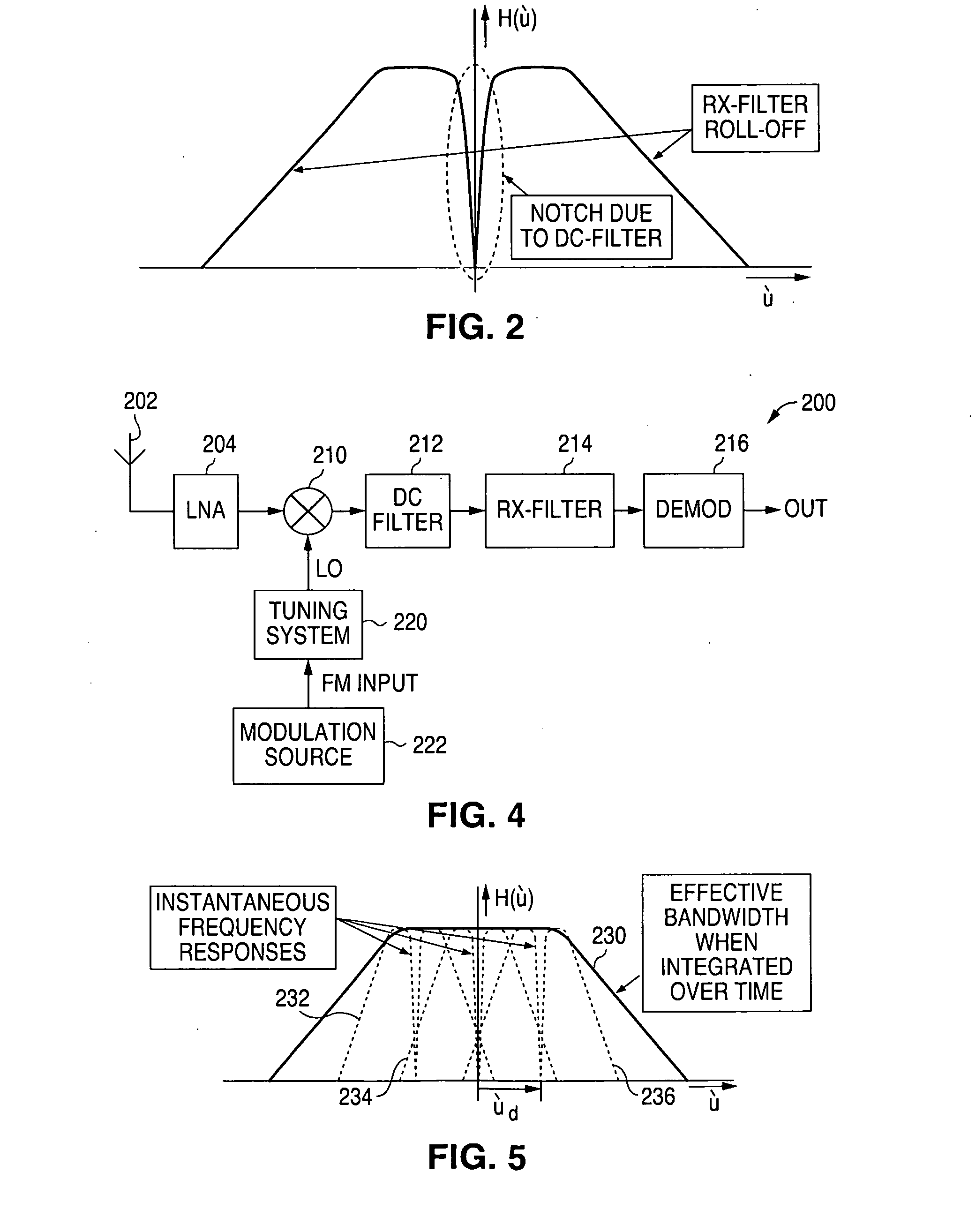
[0030]In order to achieve low cost integration, the present invention obtains a satisfactory solution by filtering out the DC signal components using simple DC filters, but with reduced low frequency signal loss compared to conventional DC filter solutions. In the present approach, two servo loops and two DACs may be excluded from the receiver circuit as compared to conventional receiver solutions. In the receiver embodiments discussed below, a Local Oscillator (LO) modulation technique is employed to reduce the low frequency signal loss caused by DC filtering.

[0031]To reduce reciprocal mixing, LO signals are traditionally optimized to have low phase noise or low jitter. In the present receiver embodiments, the LO signal is intentionally modulated, e.g. by frequency or phase modulation, across the receiver bandwidth characteristic. Modulation of the Local Oscillator signal will modulate the IF frequency such that the null in the IF pass-band caused by DC filtering (to remove the DC ...


PUM


Abstract

A modulated intermediate frequency receiver is shown having a low noise amplifier for receiving a radio frequency signal and a modulation source for generating a modulation signal. A local oscillator generates a modulated local oscillator signal in response to the modulation signal. A first mixer mixes the output of the low noise amplifier with the output of the local oscillator. The output of the mixer is DC filtered and receive bandwidth filtered before input to a demodulator that generates a demodulated received signal. Further embodiments are shown for a complex receiver and having phase or frequency modulation compensation.

Description

CROSS-REFERENCE TO RELATED PATENT APPLICATIONS[0001]This patent application claims the benefit of U.S. Provisional Patent Application No. 60 / 978,925, filed Oct. 10, 2007.FIELD OF THE INVENTION[0002]This invention pertains to radio receivers and, more particularly, intermediate frequency (IF) receiver circuits.BACKGROUND OF THE INVENTION[0003]Single chip receivers can be made low cost and small size when the receiver's selectivity filter and demodulator are completely integrated on the same integrated circuit die or chip. To obtain reasonable power consumption, required for long battery live, the intermediate frequency (IF) is chosen to be relatively low, e.g. 200 kHz, or, preferably, Zero-IF.[0004]The Direct-Conversion or so called Zero-IF receiver architecture has gained attention due to the absence of unwanted image reception, which can be problematic in Low-IF architectures. In turn, there are other problems in the Zero-IF architecture that must be solved, such as self mixing in ...

Claims


Application Information

Patent Timeline
Patent Type & Authority Applications(United States)
IPC IPC(8): H04B1/16
CPCH04B1/30
Inventor RUIJTER, HENDRICUS DE
Owner SILICON LAB INC
Why Eureka
Try Eureka