Power output system, vehicle including the same, and method of controlling power output system

a technology of power output system and output channel, which is applied in the direction of machines/engines, external condition input parameters, propulsion parts, etc., can solve the problems of insufficient reduction of pressure, inability to produce negative pressure while the engine is running, and inability to achieve bypass passage switching of exhaust gas channel from main passage to bypass passage, etc., to achieve the effect of improving reliability

Inactive Publication Date: 2009-04-16
TOYOTA JIDOSHA KK
View PDF8 Cites 11 Cited by
  • Summary
  • Abstract
  • Description
  • Claims
  • Application Information

AI Technical Summary

Benefits of technology

[0007]It is an object of the invention to provide a power output system that prevents an unburned component in exhaust gas of an internal combustion engine from being discharged to the outside, with improved reliability, and to provide a vehicle including the power output system and a method of controlling a power output system.
[0009]In the power output system as described above, the internal combustion engine is forced to be rotated, namely, motoring of the engine is effected, by driving the electric motoring mechanism using electric power supplied from the electric storage device, so that a negative pressure can be produced through the motoring and introduced into the channel switching mechanism via the pressure accumulator. Also, in the power output system, the negative pressure produced through rotation of the engine is accumulated in the pressure accumulator connected to the intake system, so that the negative pressure accumulated in the pressure accumulator can be introduced into the channel switching mechanism. Thus, in the power output system of the first aspect of the invention, the negative pressure used for switching the channel of the exhaust gas from the engine between the first exhaust gas channel and the second exhaust gas channel containing the unburned-component adsorber is selected from the negative pressure produced through motoring of the engine by the electric motoring mechanism and the negative pressure accumulated in the pressure accumulator, depending on a condition of the electric storage device and the pressure accumulation state of the pressure accumulator. Since a negative pressure is favorably and reliably provided in this manner, the possibility of a failure to introduce a negative pressure into the channel switching mechanism is reduced or eliminated. Consequently, the channel of the exhaust gas is more appropriately switched between the first exhaust gas channel and the second exhaust gas channel, and an unburned component in the exhaust gas is more reliably prevented or kept from being discharged to the outside.
[0011]According to the method as described above, a negative pressure is favorably and reliably provided, and the possibility of a failure to introduce a negative pressure into the channel switching mechanism is reduced or eliminated. Consequently, the channel of the exhaust gas is more appropriately switched between the first exhaust gas channel and the second exhaust gas channel, and an unburned component in the exhaust gas is more reliably prevented or kept from being discharged to the outside.

Problems solved by technology

However, the negative pressure cannot be produced while the engine is at rest or stopped, and, even if the engine is operated, a sufficiently reduced pressure may not be developed, depending on the operating conditions (load) of the engine.
Thus, in the internal combustion engine as described above, switching of the exhaust gas channel from the main passage to the bypass passage may not be accomplished because of a shortage or lack of the negative pressure when the switching is to be done, and an unburned component, such as hydrocarbon, in the exhaust gas may be discharged to the outside without being converted into harmless substances.

Method used


Image

  • Power output system, vehicle including the same, and method of controlling power output system
  • Power output system, vehicle including the same, and method of controlling power output system
  • Power output system, vehicle including the same, and method of controlling power output system

Examples


Embodiment Construction

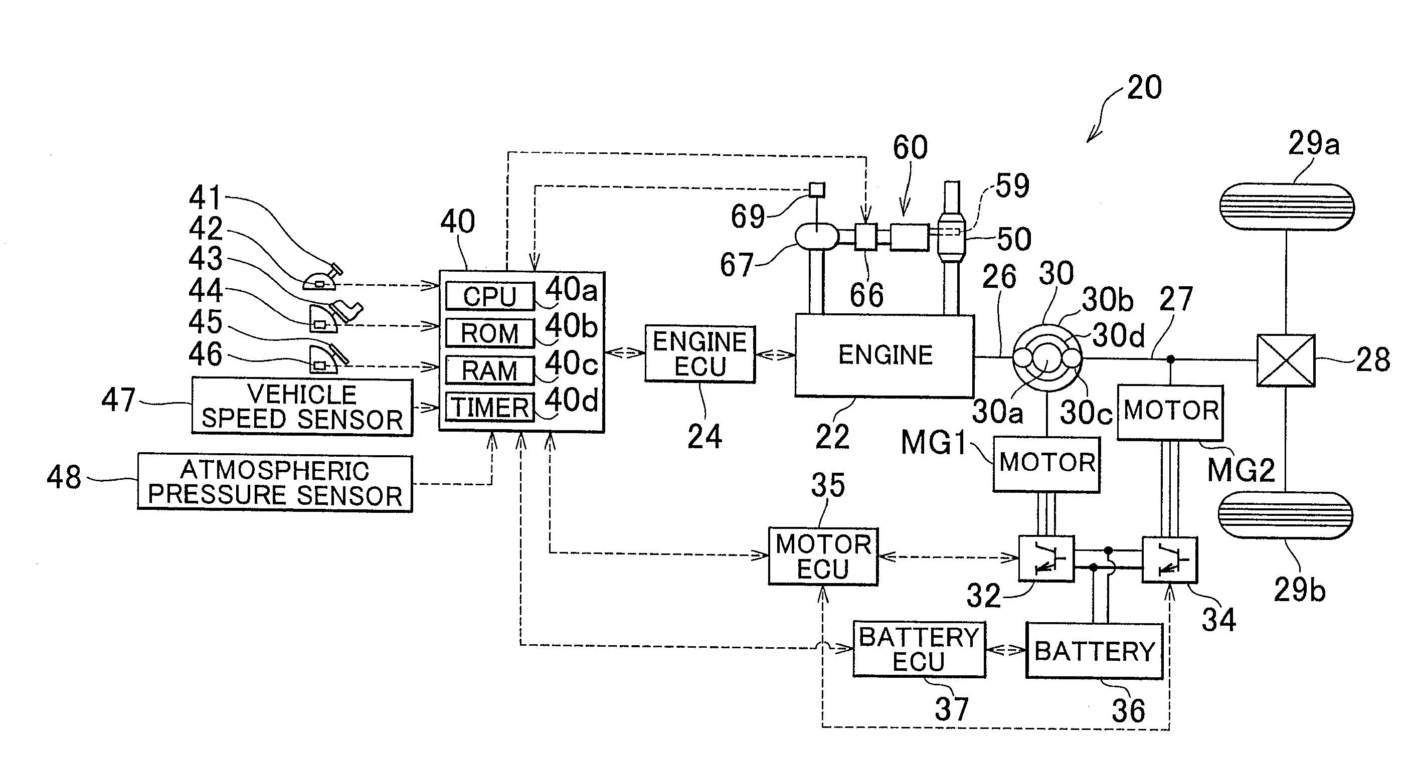
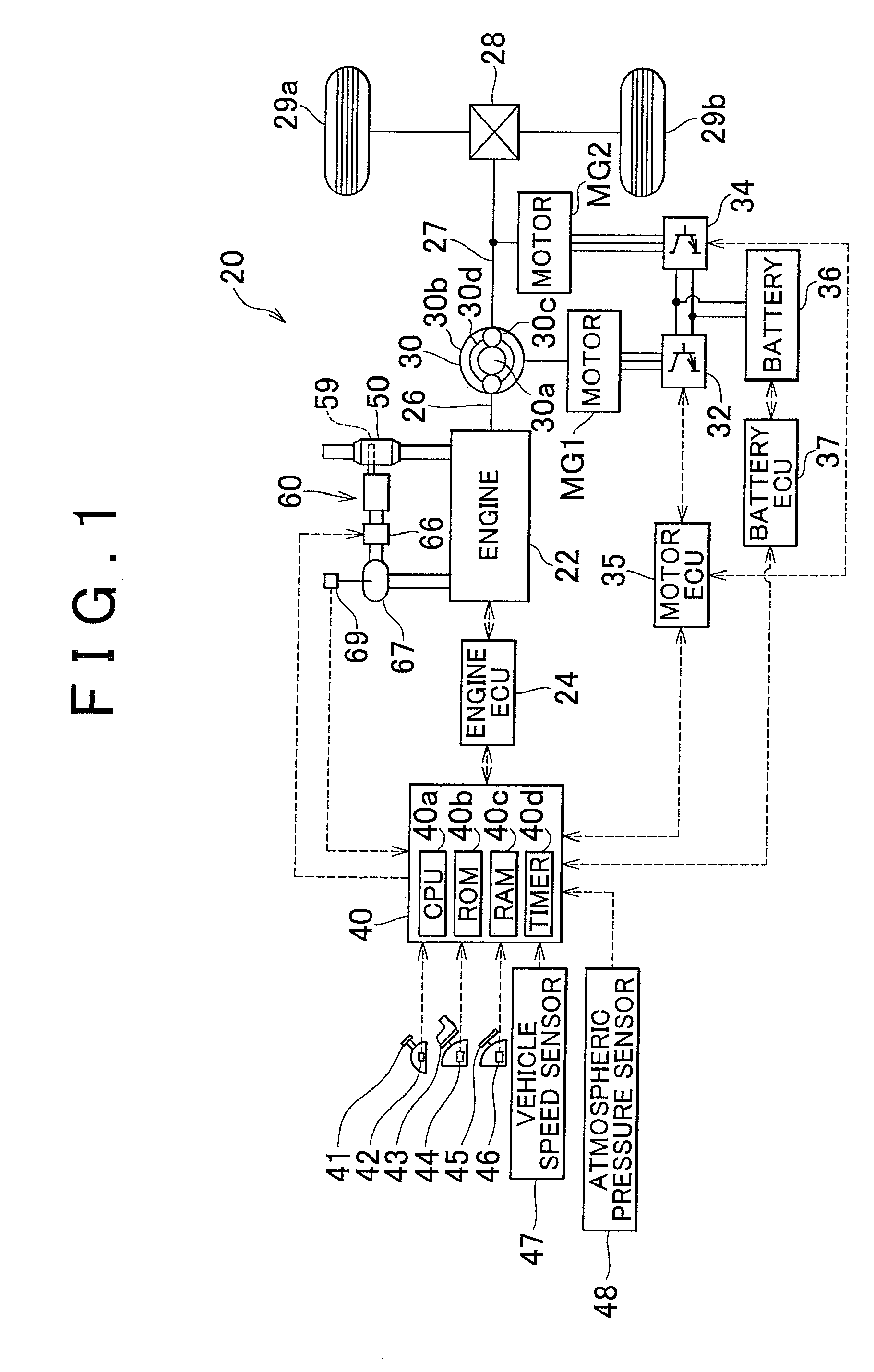
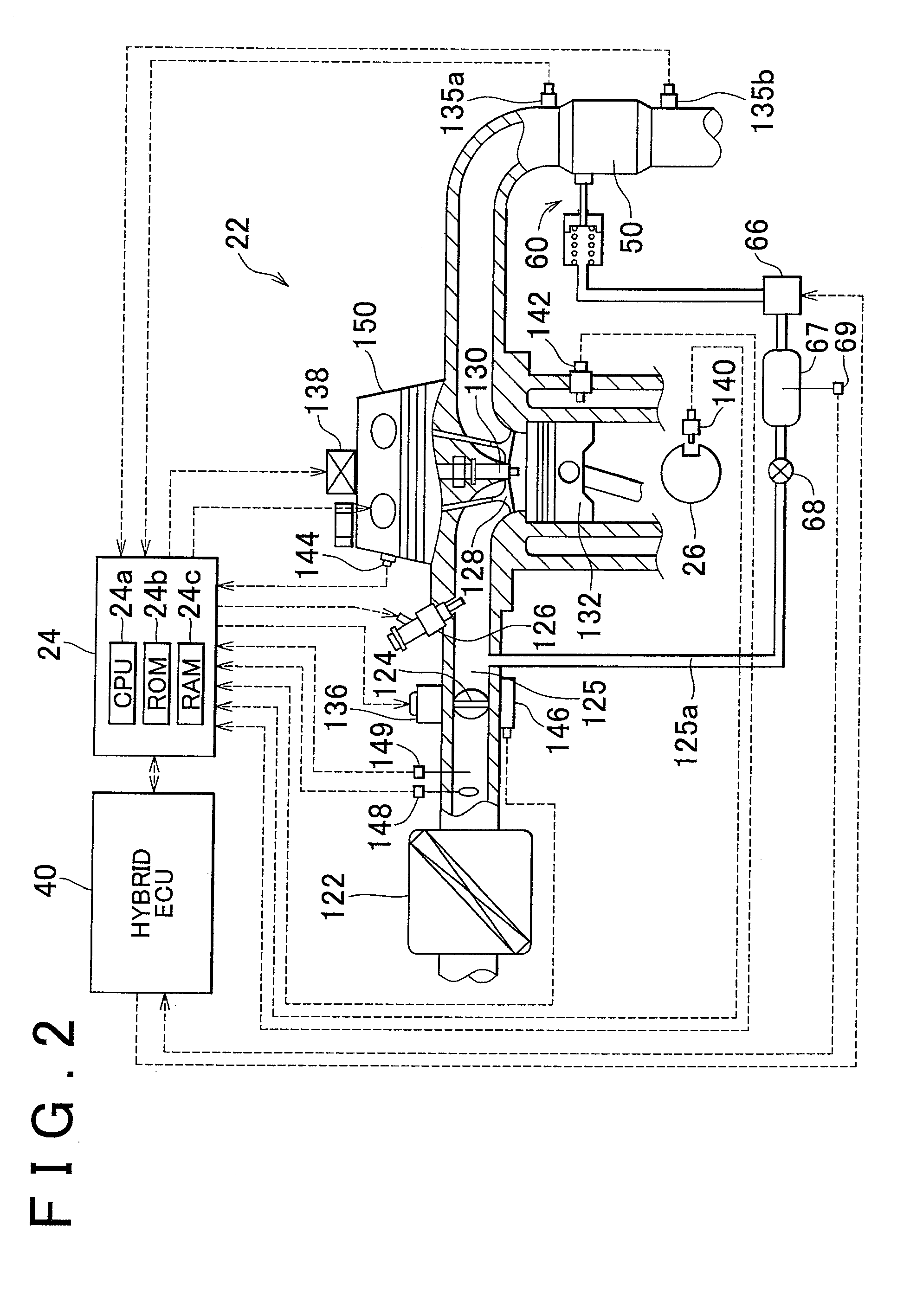
[0020]FIG. 1 schematically illustrates the construction of a hybrid vehicle 20 provided with a power output system according to one embodiment of the invention. FIG. 2 schematically illustrates the construction of an engine 22 installed on the hybrid vehicle 20. As shown in FIG. 1, the hybrid vehicle 20 of this embodiment includes the engine 22, a 3-axes-type power distribution / integration mechanism 30 connected via a damper (not shown) to a crankshaft 26 as an output shaft of the engine 22, a motor MG1 connected to the power distribution / integration mechanism 30 and capable of generating electric power, a motor MG2 connected to the power distribution / integration mechanism 30, and an electronic control unit (which will be called “hybrid ECU”) 40 for controlling the whole system of the hybrid vehicle 20.

[0021]The engine 22 is constructed as an internal combustion engine capable of delivering power by using a hydrocarbon-base fuel, such as gasoline or light oil. In the engine 22 as sh...


PUM


Abstract

A power output system that provides power to a driveshaft is provided which includes an internal combustion engine, an electric motoring mechanism, an electric storage device, a first exhaust gas channel that guides exhaust gas from the engine directly to an exhaust gas purifying catalyst, a second exhaust gas channel which guides the exhaust gas from the engine to the exhaust gas purifying catalyst via an unburned-component adsorber, a channel switching mechanism operable to switch a channel of the exhaust gas from the engine between the first exhaust gas channel and the second exhaust gas channel, a pressure accumulator operable to accumulate therein a negative pressure produced through rotation of the engine, a negative-pressure introducing / releasing mechanism that selectively permits and inhibits introduction of the negative pressure from the pressure accumulator into the channel switching mechanism, and a controller that controls the electric motoring mechanism and the negative-pressure introducing / releasing mechanism.

Description

INCORPORATION BY REFERENCE[0001]The disclosure of Japanese Patent Application No. 2007-265415 filed on Oct. 11, 2007, including the specification, drawings and abstract, is incorporated herein by reference in its entirety.BACKGROUND OF THE INVENTION[0002]1. Field of the Invention[0003]The invention relates to a power output system that provides power to a driveshaft, a vehicle including the power output system, and a method of controlling the power output system.[0004]2. Description of Related Art[0005]Japanese Patent Application Publication No. 2001-41026 (JP-A-2001-41026) discloses an internal combustion engine including a HC adsorption apparatus provided upstream of a catalytic converter in an exhaust passage. The HC adsorption apparatus of this engine includes a main passage, a switching valve that opens and closes the main passage, and a bypass passage that bypasses the main passage, and a HC adsorbent that adsorbs hydrocarbon (HC) contained in exhaust gas is disposed in the by...

Claims


Application Information

Patent Timeline
Patent Type & Authority Applications(United States)
IPC IPC(8): F02D45/00
CPCB60K1/02Y10S903/93B60K6/442B60K6/445B60K6/448B60K6/485B60K6/52B60L2240/445B60W10/06B60W10/08B60W20/00B60W2510/0676B60W2510/068B60W2510/0685B60W2510/244B60W2510/246B60W2520/10B60W2540/10B60W2540/12B60W2550/12F01N3/0807F01N3/0835F01N3/0878F01N2390/04F02N11/0818F02N11/0829F02N2200/026Y02T10/54Y02T10/6226Y02T10/6234Y02T10/6243Y02T10/6265Y02T10/6286Y02T10/48Y02T10/20Y02T10/6239B60K6/365B60W2555/20Y02T10/12Y02T10/40Y02T10/62B60K6/44B60W20/15
Inventor SASAKI, TOSHITAKE
Owner TOYOTA JIDOSHA KK
Why Eureka
Try Eureka