
Method and an engagement sensor device for engagement measurement for a machine tool

Inactive Publication Date: 2009-04-23
ALFING KESSLER SONDERMASCH
View PDF2 Cites 9 Cited by
  • Summary
  • Abstract
  • Description
  • Claims
  • Application Information

AI Technical Summary

Benefits of technology

[0009]One advantage of this arrangement is that the sensor may for example be arranged in a stationary manner. Accordingly its wear rate is low and it is furthermore readily replaced. Furthermore the sensor is not subject to external forces and only measures into any gap present.
[0013]The clamping device is preferably able to be shifted in relation to the frame of the machine tool, and for example may be turned in relation to it. In this connection the invention is also particularly advantageous, since the sensor device may be arranged stationarily in relation to the movable clamping device. Accordingly the clamping device can be attached for example to a machine bed, to a holder or to a rotary support for the movable clamping device or the like. Thus the replacement of the sensor device is simplified.
[0015]A stationary sensor device does however bring the advantage that for example a tool change or a workpiece change may take place more rapidly.

Problems solved by technology

A disadvantage in this arrangement is that the planar engagement sensor is arranged on the moving spindle rotor so that the transmission of the evaluation signal is relatively complex.
Furthermore the planar engagement sensors are relatively difficult to replace.

Method used


Image

  • Method and an engagement sensor device for engagement measurement for a machine tool
  • Method and an engagement sensor device for engagement measurement for a machine tool
  • Method and an engagement sensor device for engagement measurement for a machine tool

Examples


Embodiment Construction

[0047]In the following description of working examples similar or functionally equivalent component are provided with the same reference numerals.

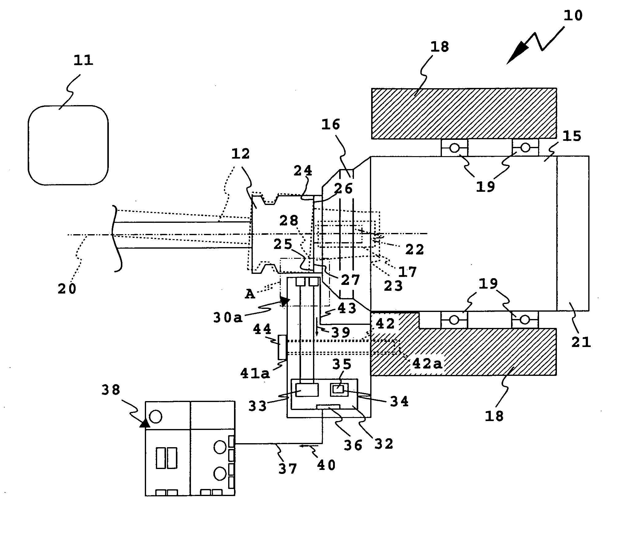
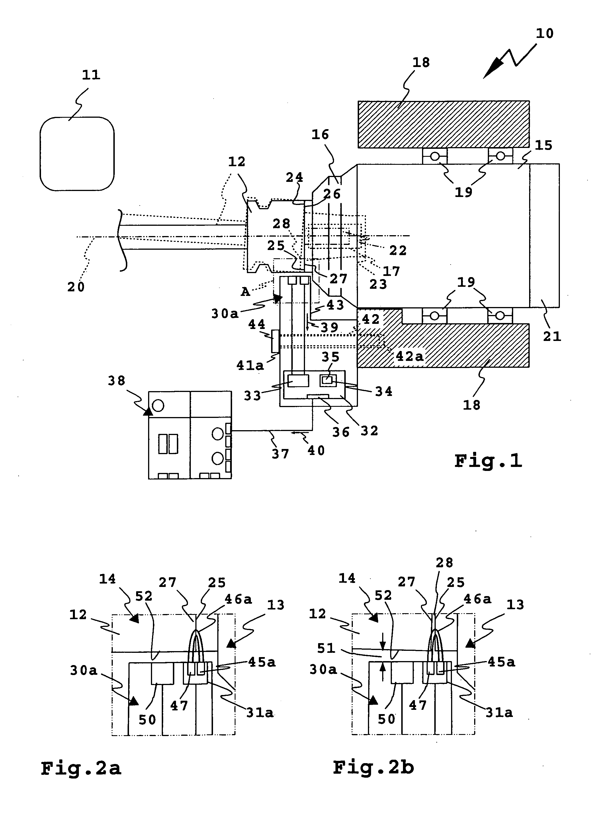
[0048]A machine tool 10 only illustrated diagrammatically in part serves for processing workpieces 11, which are also only indicated diagrammatically, as for example castings or other metal parts, by means of tools 12. The tool 12 is a tool for chip removal as for example a milling cutter or a lathe tool. The tool 12 constitutes a clamped object 14, which is held by a clamping device 13 of the machine tool 10. The clamping device 13 is provided on a spindle rotor 16 of a spindle 15. The tool 12 is inserted into a tool socket 17 in the spindle 15 and held fast in it.

[0049]The spindle rotor 16 is rotatably mounted on a spindle holder 18 with the aid of a spindle bearings 19 for rotation about an axis 20 of rotation 20. The spindle 15 is driven by a motor 21.

[0050]The shank 22 of the tool 12 is clamped in a tool holder 23 of the clamping devi...


PUM

PropertyMeasurementUnit
Distanceaaaaaaaaaa
Magnetismaaaaaaaaaa
Inductive effectaaaaaaaaaa

Abstract

In a method and an engagement sensor device for engagement measurement for a machine tool for processing workpieces using tools or a laser the machine tool possesses a clamping device with a clamping face for clamping an object, in particular a tool or a workpiece and the engagement sensor device is provided for the measurement or engagement of a face of clamped object at the clamping face or any gap between the face of the clamped object and the clamping face. The sensor device comprises at least one engagement sensor, arranged to the side of the clamping face, with a measurement range aligned in the direction of the gap or of the clamping face for the detection of an electrical or magnetic stimulation field, such field extending between the face of clamped object and the clamping face and being able to be influenced by any gap, the measurement range extending essentially along the clamping face in accordance with a depth direction of any gap or parallel to the clamping face.

Description

BACKGROUND OF THE INVENTION[0001]The invention relates to a method and an engagement sensor device for engagement measurement for a machine tool for processing workpieces using tools or a laser, in the case of which the machine tool possesses a clamping device with a clamping face for clamping an object, in particular a tool or a workpiece and the engagement sensor device is provided for the measurement or engagement of a face of the clamped object at the clamping face or any gap between the face of the clamped object and the clamping face.[0002]The machine tool is for example a milling or drilling machine or a lathe, which machines the workpiece by chip removal.THE PRIOR ART[0003]A machine tool with a sensor device for measurement of engagement of a clamped object, as for example a workpiece, is disclosed in the German patent publication DD 264 625 A1. By the application of a workpiece to planar engagement elements the latter are short circuited. The planar engagement elements are ...

Claims


Application Information

Patent Timeline
IPC IPC(8): G01B5/14B23B49/00
CPCY10T408/21B23Q17/002
Inventor MUELLNER, RALF
Owner ALFING KESSLER SONDERMASCH
Learn More