Apparatus and methods for improving the energy efficiency of dryer appliances

a dryer and energy efficiency technology, applied in the direction of dryers, lighting and heating apparatus, furnaces, etc., can solve the problems of affecting the direction of exhaust air routing, etc., and achieve the effects of reducing the overall energy consumption, improving the efficiency of the dryer, and reducing the cost of operation

Inactive Publication Date: 2009-04-23
FAIR ROBERT WOOD
View PDF40 Cites 39 Cited by
  • Summary
  • Abstract
  • Description
  • Claims
  • Application Information

AI Technical Summary

Benefits of technology

[0005]The present invention provides a apparatus, in several embodiments, for recovering energy used for heating drying air, for eliminating the use of conditioned air for dryer intake air, and, generally, significantly improving the efficiency of the

Problems solved by technology

Routing of exhaust air is, however, affected by whether bui

Method used


Image

  • Apparatus and methods for improving the energy efficiency of dryer appliances
  • Apparatus and methods for improving the energy efficiency of dryer appliances
  • Apparatus and methods for improving the energy efficiency of dryer appliances

Examples


Embodiment Construction

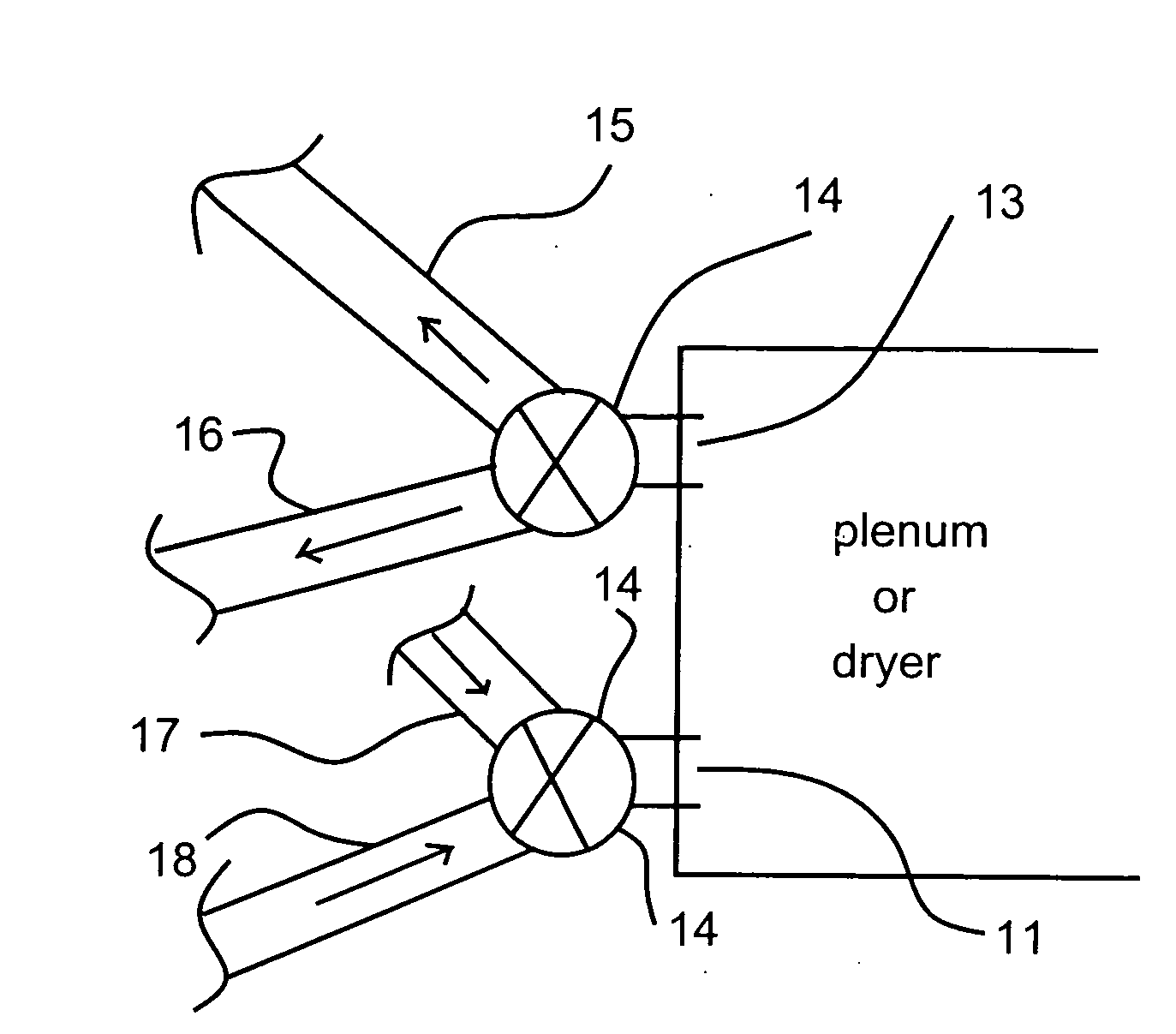
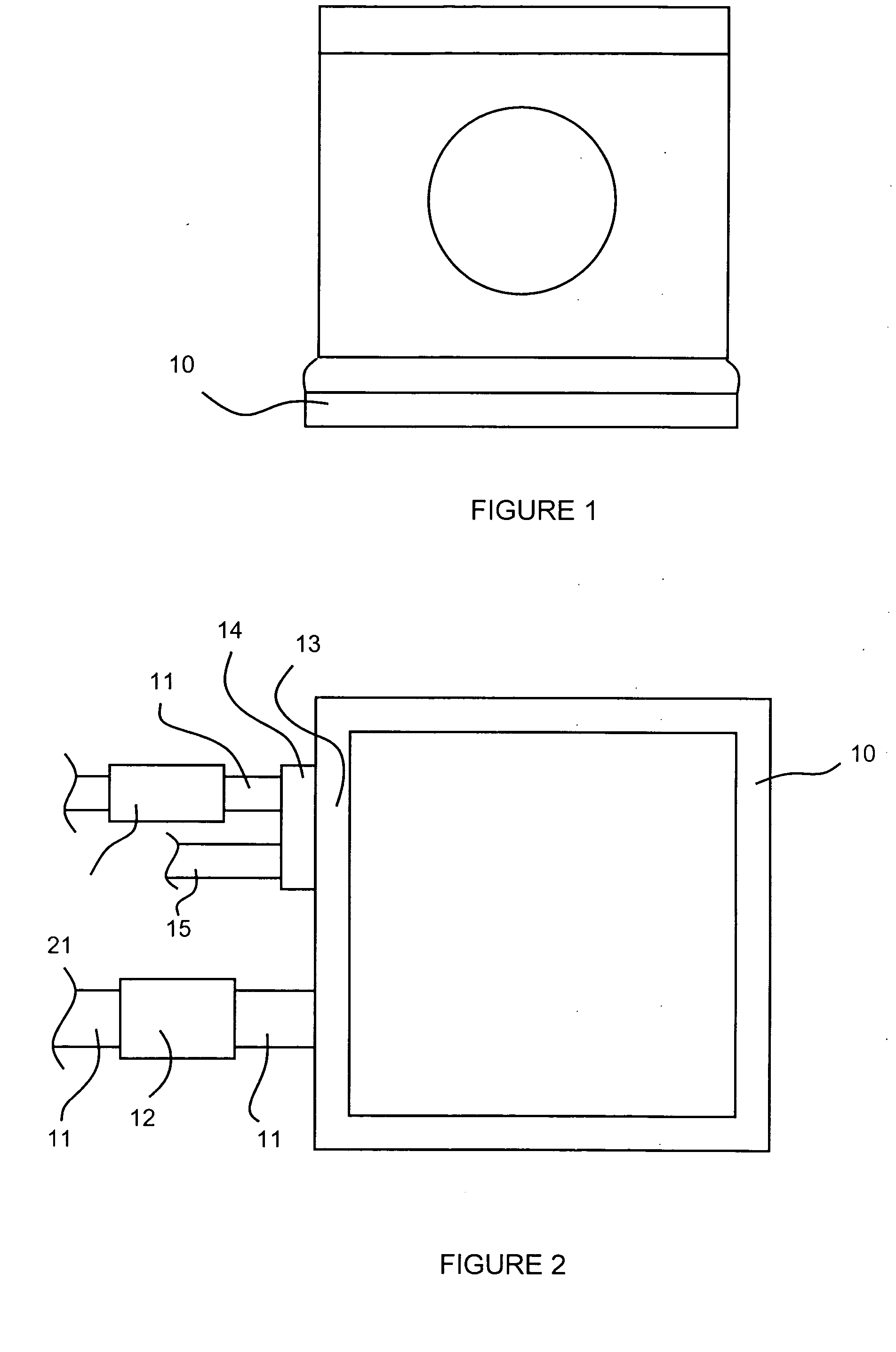
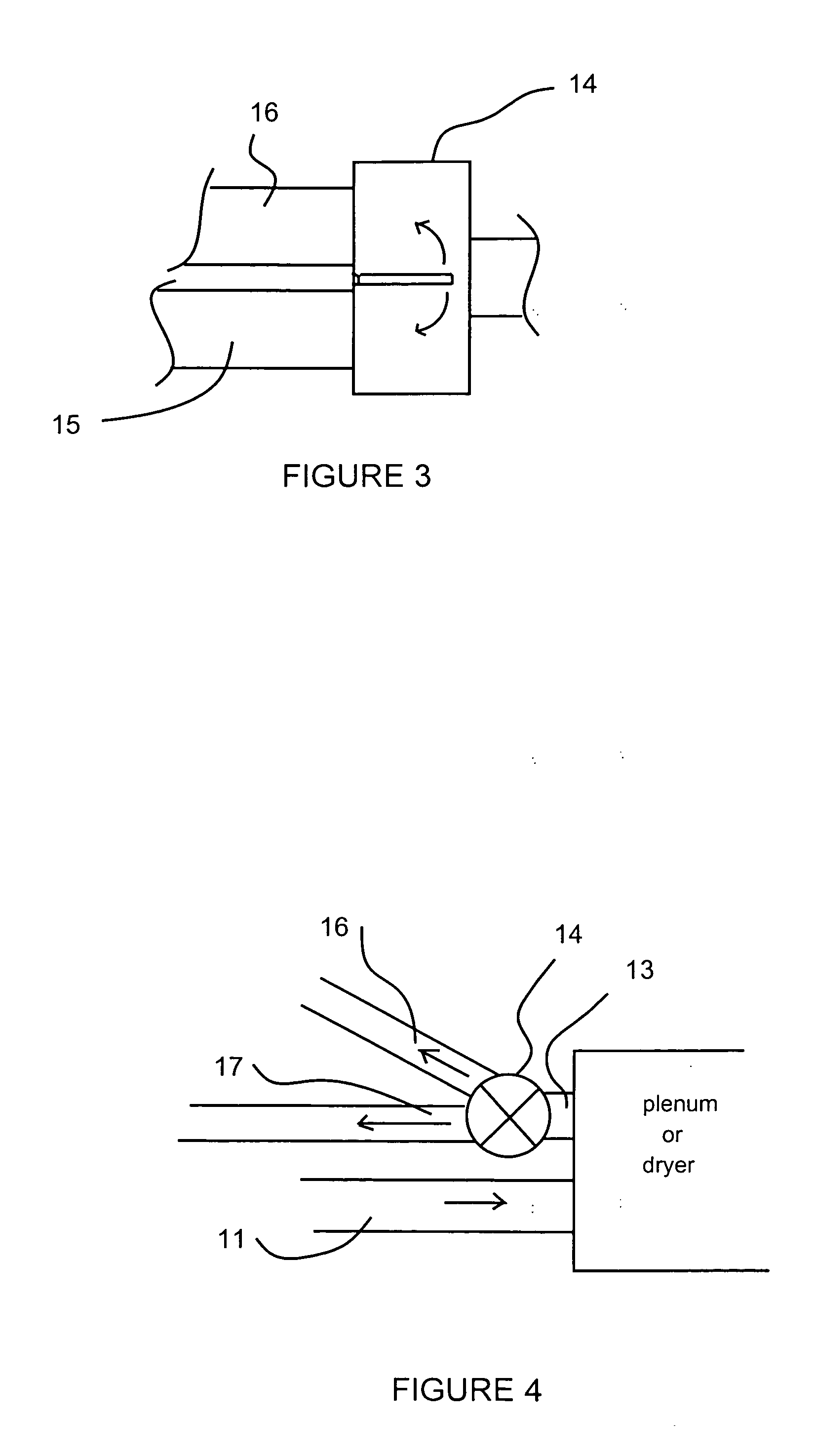
[0031]In most conventional electrically heated dryers, the vast majority, if not the totality, of the intake air is drawn into the dryer at the base of the dryer cabinet, and in most conventional gas heated dryers the intake air is drawn into the dryer through the rear wall of the dryer cabinet. Referring now to the accompanying drawing figures, an embodiment of the apparatus of the invention for retrofitting a conventional electrically heated dryer for the use of exterior air as intake air includes a base plenum 10 to be disposed around the base of the dryer, with a generally air tight seal between the plenum and the sides of the dryer cabinet above the base, and above the intake point for a gas dryer, and with a generally air tight seal between the plenum and the floor or other surface upon which the dryer base rests. Any effective sealing means may be used within the scope of the invention, such as a rubber gasket or a bellows and tape. Alternatively, the base plenum may be struc...


PUM


Abstract

Apparatus for improving the efficiency of dryer appliances that utilize heated air for drying and are disposed within a residence or other closed conditioned space includes an intake air duct connected between the dryer appliance and a source of intake air outside the conditioned space, an exhaust outlet diverter valve to receive exhaust air from the dryer and direct the exhaust air for release within the conditioned space or alternatively outside the conditioned space. Alternative embodiments provide for drawing intake air from more than one source, with and without heat exchange, for releasing heated air to more than one location, including into a heating system return air duct, either directly or through a heat exchanger. A method of controlling the operation of the apparatus is also provided.

Description

RELATED APPLICATION DATA[0001]This application claims the benefits of U.S. Provisional Patent Application No. 60 / 994,575, filed Sep. 20, 2007.FIELD OF THE INVENTION[0002]The present invention generally relates to apparatus and methods for substantially improving the efficiency with which thermal energy is utilized within a conditioned space, particularly but not limited to residential spaces, for the operation of appliances associated with that space; and in its most preferred embodiments relates to improving the thermal efficiency of clothes dryer appliance within or adjacent to a conditioned space with particular regard to sources of thermal energy, use of that energy in the appliance, and capture of previously under-utilized waste energy from the appliance for beneficial use within the conditioned space.BACKGROUND[0003]Clothes dryer appliances operate by forcing warm air over and through the clothes to be dried so as to evaporate moisture from the clothes, and then exhausting the...

Claims


Application Information

Patent Timeline
IPC IPC(8): F26B3/02F26B19/00F26B25/00F26B21/12
CPCF26B23/002F26B21/00Y02P70/10
Inventor FAIR, ROBERT WOOD
Owner FAIR ROBERT WOOD
Why Eureka
Try Eureka