Rotating electrical machinery
- Summary
- Abstract
- Description
- Claims
- Application Information
AI Technical Summary
Benefits of technology
Problems solved by technology
Method used
Image
Examples
third embodiment
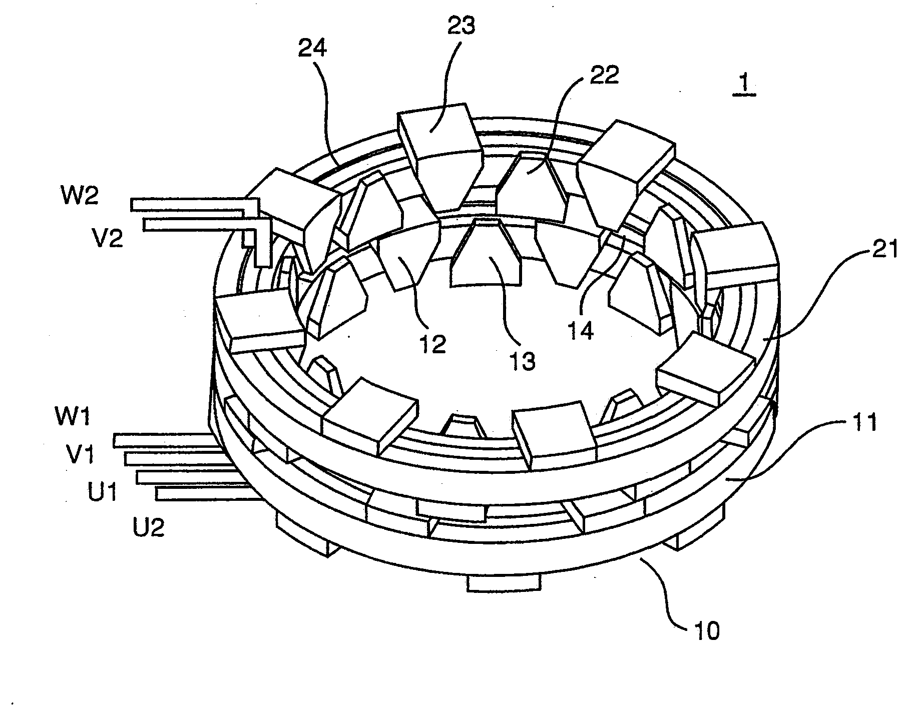
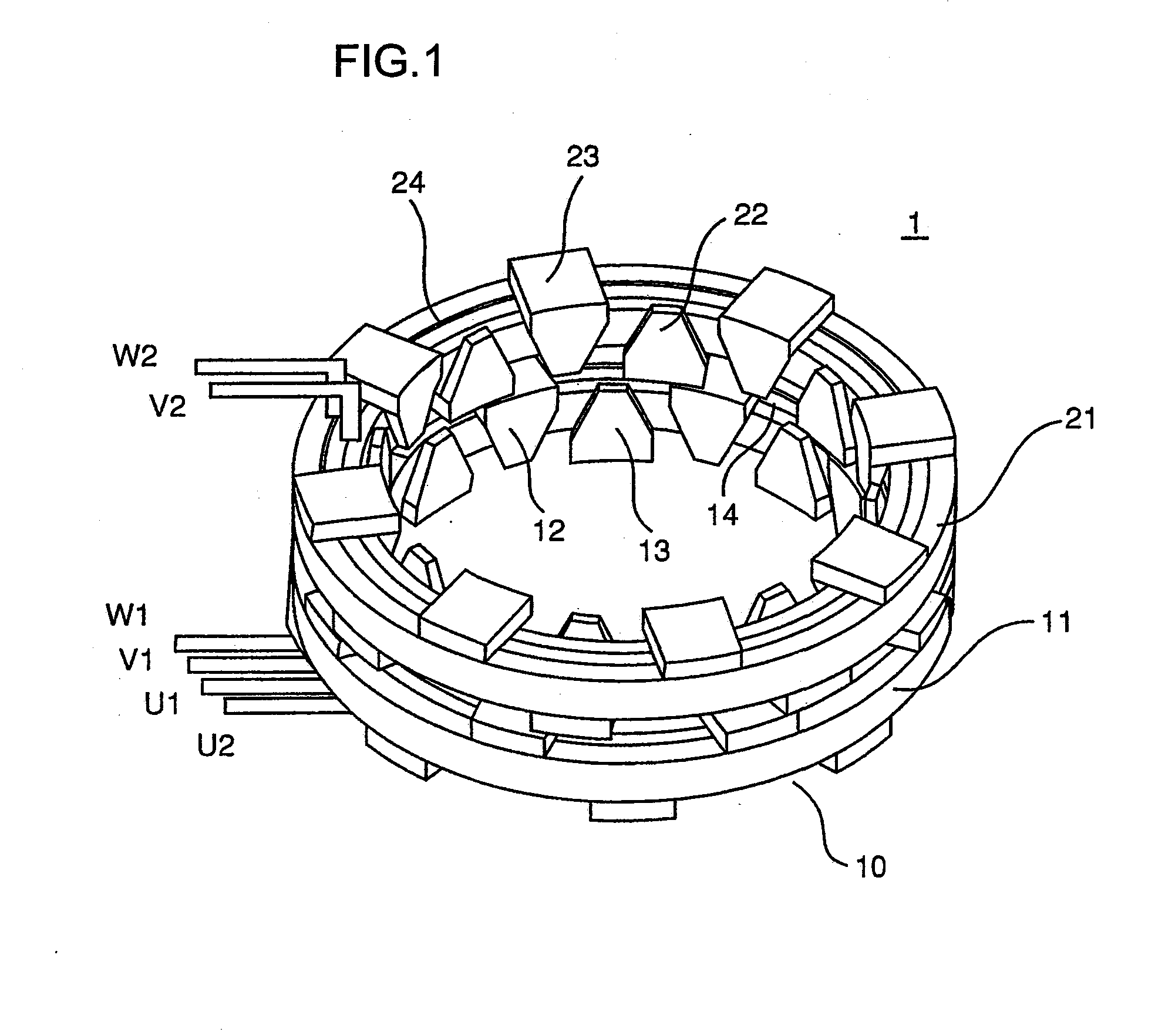
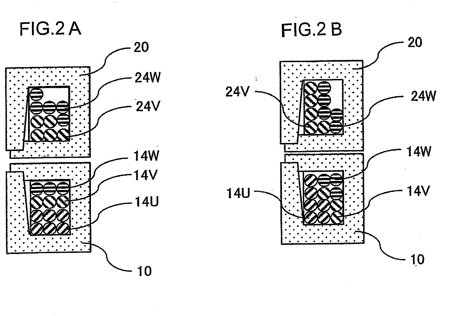
[0136]The third embodiment of the present invention is now described. The present invention maybe adopted in multiple phase coils assuming four or more different phases, as well as in conjunction with three phase coils.
[0137]In the following description, too, ØA, and ØB represent magnetic fluxes interlinking with single turn coils inside the A core 10 and the B core 20 respectively. An explanation is now given with regard to M-phase coils. Magnetic flux linkages Φk, . . . Φm interlinking with the individual coils are expressed as;
Φ1=NA1ØA+NB1ØB (21)
Φk=NAkØA+NBkØB (22)
ΦM=NAMØA+NBMØB (23)
[0138]The numbers of coil turns NA1, NA2, . . . NAM and the numbers of coils NB1, NB2, . . . NBM are determined so that the electrical phases of the magnetic flux linkages decrease in sequence by 2π / M at a time starting at Φ1. The embodiment is described by assuming that the magnetic fluxes ØA and ØB manifest a phase difference relative to each other by 90°. By defining ØA and ØB as ØA=Ø0 sin ωt...
fourth embodiment
[0144]FIGS. 12A˜12B illustrate another embodiment of the present invention. Apart from the features described below, the embodiment is similar to the first embodiment.
[0145]In the embodiment described in detail below, the claw poles and the core backs at the A core 10 and the B core 20 in the stator unit 1 are constituted with laminated core blocks. FIG. 12A shows one of the iron sheet blank 201 used to constitute a laminated core block, which, in turn, is used to form a claw pole 212. The width of the claw, smallest at the front end, gradually increases toward the base along the axial direction and the claw achieves an R-shape at the base, since the sectional area at the base must be set greater than the sectional area at the front end to accommodate the magnetic flux flowing in from the rotor side of the claw pole 212 and traveling toward the base. FIG. 12B shows an assembly formed by layering a plurality of blanks, one of which is shown in FIG. 12A. The shapes of the blanks lamin...
fifth embodiment
[0153]Next, another embodiment of the present invention is described in reference to FIGS. 19A˜19C. The embodiment is identical to the first embodiment described above except for the specific features explained below.
[0154]In the previous embodiment, the holding plates are each provided as an independent component, and are assembled as part of the stator unit. In this embodiment, however, a portion to constitute a holding plate is directly formed at a stator core block. FIGS. 19A˜19C each show a half stage stator 3 corresponding to a given stage. The structure of the half stage stator shown in FIG. 19A is similar to that shown in FIG. 13B. FIG. 19B shows a structure with a thin holding plate portion 230b covering the coil installation surfaces of the stator core blocks. FIG. 19C illustrates how a stator core assuming such a structure may be formed. FIG. 19C schematically illustrates a die unit. A lower die 231 to be used as a base includes a holding portion with which the laminated ...
PUM
 Abstract
Description
Claims
Application Information
 - Generate Ideas
- Intellectual Property
- Life Sciences
- Materials
- Tech Scout
- Unparalleled Data Quality
- Higher Quality Content
- 60% Fewer Hallucinations
Browse by: Latest US Patents, China's latest patents, Technical Efficacy Thesaurus, Application Domain, Technology Topic, Popular Technical Reports.
© 2025 PatSnap. All rights reserved.Legal|Privacy policy|Modern Slavery Act Transparency Statement|Sitemap|About US| Contact US: help@patsnap.com


