System and methods for radar and communications applications

a communication application and radar technology, applied in the field of radar and communications applications, can solve the problems of high repair cost, high cost, and high mass per unit of phased array antennas, and achieve the effect of low areal density

Active Publication Date: 2009-04-23
THE BOEING CO
View PDF8 Cites 23 Cited by
  • Summary
  • Abstract
  • Description
  • Claims
  • Application Information

AI Technical Summary

Benefits of technology

[0007]The embodiments of the present system and methods for radar and communications applications have several features, no single one of which is solely responsible for their desirable attributes. Without limiting the scope of the present embodiments as expressed by the claims that follow, their more prominent features now will be discussed briefly. After considering this discussion, and particularly after reading the section entitled “Detailed Description”, one will understand how the features of the present embodiments provide advantages. These include a thin backplane, low areal density, ease of transport and ease of disassembly and reassembly as part of normal operation due to the array including individually removable and replaceable unit cells with no interconnections except the mechanical.

Problems solved by technology

These include: high cost, difficulty of transporting large arrays (because large arrays must be handled as unitary entities—because of contiguous signal, control and / or power distribution manifolds), high repair costs (typically about five percent of modules may fail before modules must be replaced), and high phased array antenna areal density (mass per unit aperture area).
Maximizing the cost benefits of commercial assembly (for planar circuit boards) has led to more complex multi-layer circuit boards being employed.
When the requisite number of failures in an antenna has occurred and the modules need to be replaced, whole panels are replaced, by disassembling the antenna, with the attendant intra-antenna interconnect issues.
However fiber optics cannot carry the power levels necessary to operate the array, thus maintaining the monolithic array backplane for power distribution.
In the case of fiber optics the weight is decreased along with system maturity while cost is increased because of the more immature photonics technologies.
Routine fold / disassembly / deploy operations are not possible in current high frequency systems.
Even with photonics, the array cannot be disassembled for shipping / transport then reassembled for operation unless a complete recalibration is performed each time.
Therefore, the backplane is transported in one piece, which is problematic for highly mobile users who must then fall back on non-array antenna solutions.

Method used


Image

  • System and methods for radar and communications applications
  • System and methods for radar and communications applications
  • System and methods for radar and communications applications

Examples


Embodiment Construction

”, one will understand how the features of the present embodiments provide advantages. These include a thin backplane, low areal density, ease of transport and ease of disassembly and reassembly as part of normal operation due to the array including individually removable and replaceable unit cells with no interconnections except the mechanical.

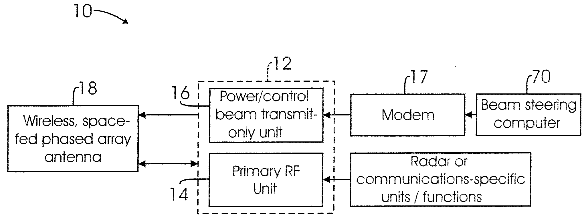
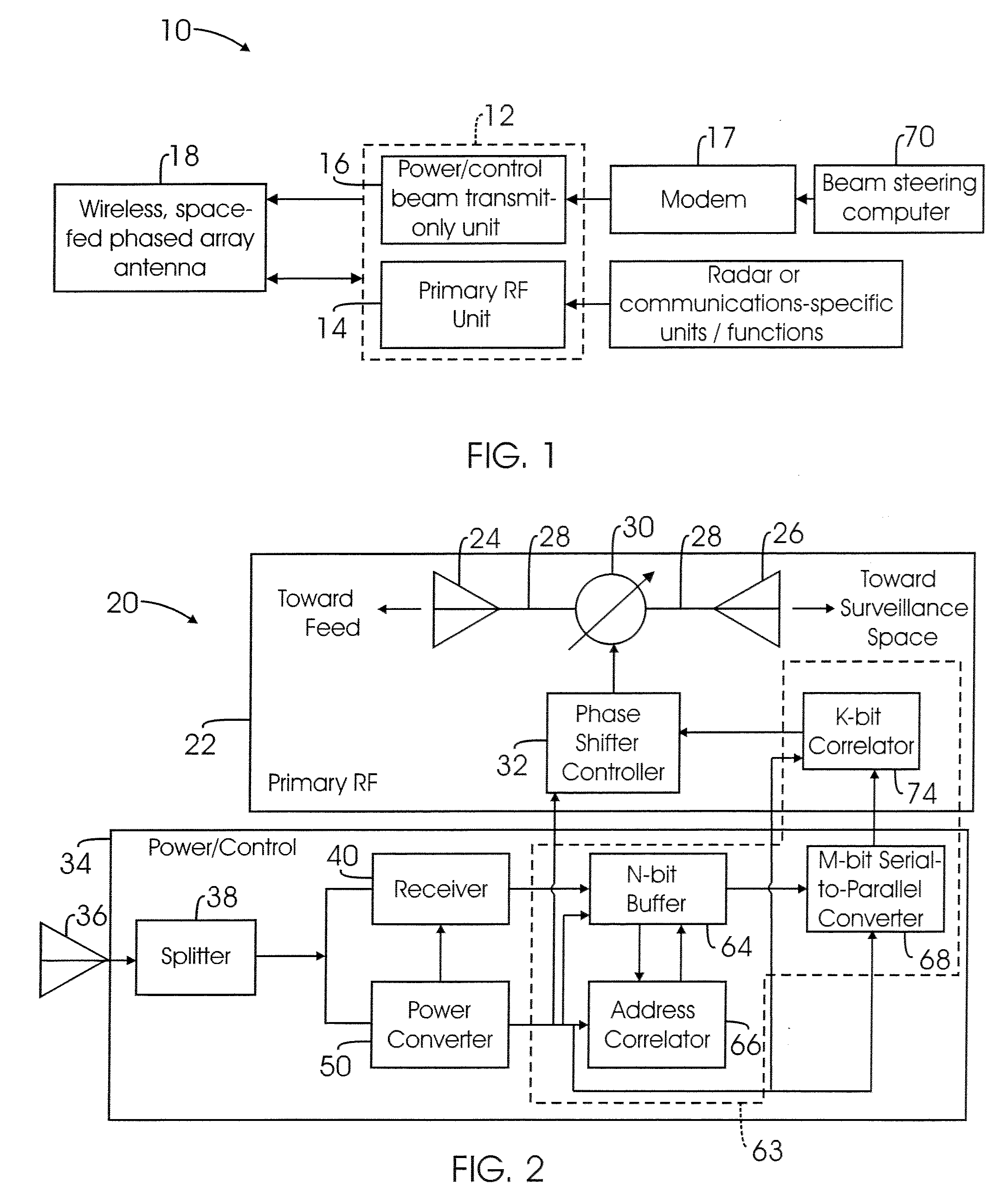
[0008]One embodiment of the present system for radar and communications applications comprises a wireless, space-fed, phased array of antennas including a plurality of unit cells. A first one of the unit cells includes a first one of the antennas. The first unit cell further includes a unit cell command interpreter configured to receive a command, determine whether the command is intended for the first unit cell, and relay the command to logic for enabling a phase shift controller of the first antenna.

[0009]One embodiment of the present methods for radar or communications applications comprises the step of wirelessly beaming microwave power f...


PUM


Abstract

A system and methods for radar and communications applications. In one embodiment the present system comprises a wireless, space-fed, phased array of antennas including a plurality of unit cells. A first one of the unit cells includes a first one of the antennas and a unit cell command interpreter configured to receive a command, determine whether the command is intended for the first unit cell, and relay the command to logic for enabling a phase shift controller of the first antenna. In one embodiment the present methods comprise the step of wirelessly beaming microwave power from a power and control beam transmit unit to illuminate a wireless, space-fed, phased array of antennas including a plurality of unit cells. The method further comprises the steps of beaming a command to the array and converting the microwave power into direct current within a first one of the unit cells. The first unit cell includes a first one of the antennas. The method further comprises the steps of supplying the direct current to components of the first unit cell to power the first unit cell, receiving the command within the first unit cell, determining whether the command is intended for the first unit cell, and relaying the command to logic for enabling a phase shift controller of the first antenna.

Description

BACKGROUND[0001]1. Technical Field[0002]The present disclosure relates to radar and communications applications and in particular to those including phased arrays of antennas.[0003]2. Description of Related Art[0004]A phased array is a group of antennas in which the relative phases of the respective signals feeding the antennas are varied in such a way that the effective radiation pattern of the array is reinforced in a desired direction concomitantly with pattern control in undesired directions. Phased arrays come in several basic forms but are typically characterized by: an ensemble of radiating elements (the ‘antennas’ referred to above), a means to illuminate the elements that operates reciprocally as a beamformer (also called a feed network or manifold), an amplification, phasing and control / logic layer, an RF signal, timing and control, a power distribution layer (or mainfold), and associated support structure. Phased array antennas are almost exclusively assembled as monolith...

Claims


Application Information

Patent Timeline
Patent Type & Authority Applications(United States)
IPC IPC(8): H01Q3/26H01Q9/04
CPCG01S7/003G01S2013/0254H01Q1/248H01Q21/0087H01Q21/0018H01Q21/0025H01Q3/26
Inventor SEGO, DANIEL J.
Owner THE BOEING CO
Why Eureka
Try Eureka