
Flow Machine

a flow machine and flow tube technology, applied in machines/engines, stators, liquid fuel engines, etc., can solve the problems of insufficient cooling of the rear region of the wall, unacceptably high quantity of cool fluid to be supplied, etc., and achieve the effect of efficient cooling of the wall

Inactive Publication Date: 2009-04-23
SIEMENS AG
View PDF5 Cites 2 Cited by
  • Summary
  • Abstract
  • Description
  • Claims
  • Application Information

AI Technical Summary

Benefits of technology

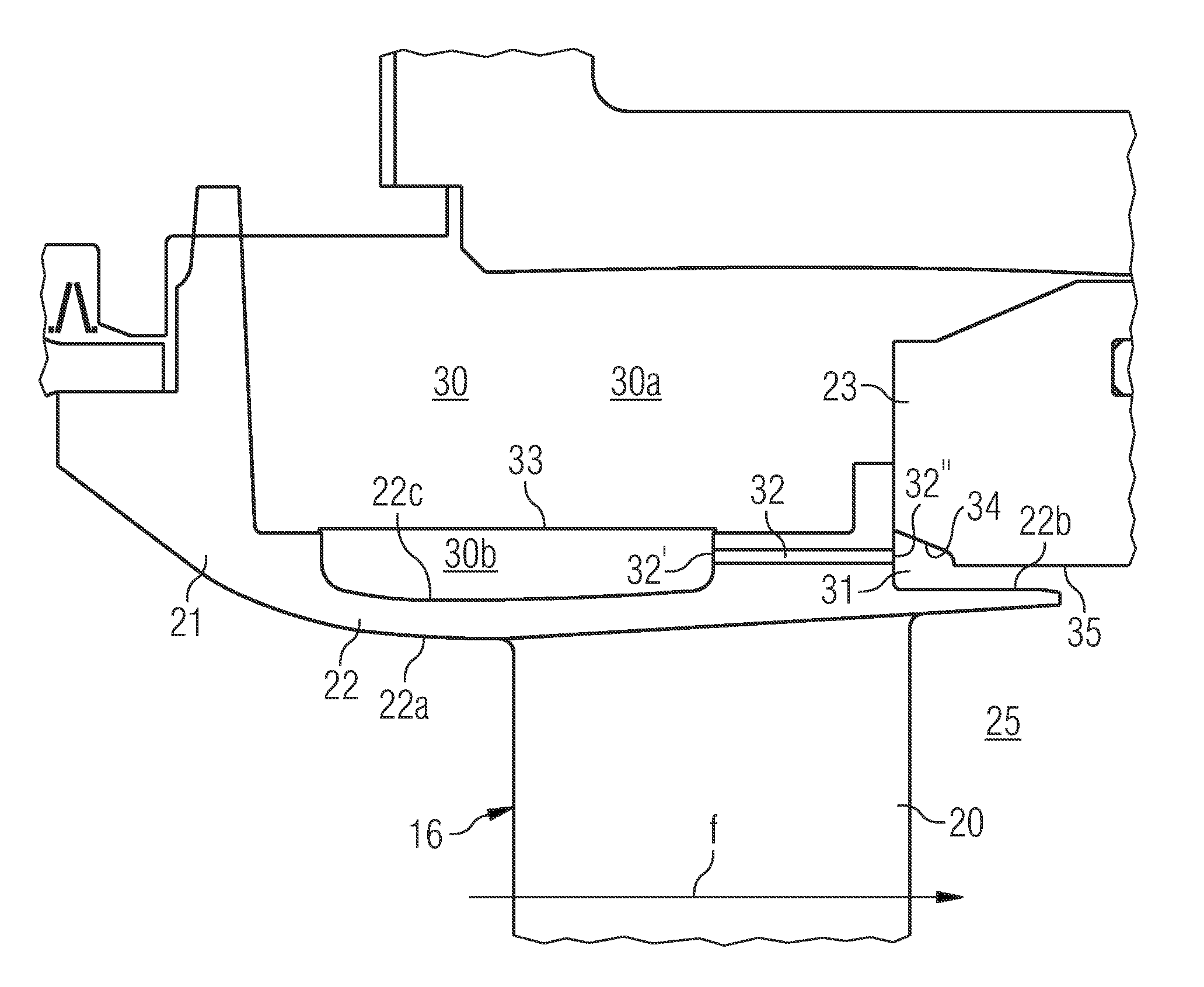
[0008]This object is achieved by the flow machine initially defined, which is characterised in that the deflection surface has a concave surface portion, which is concave in said extension plane and adapted to re-direct the second fluid that leaves the duct so that it impinges substantially directly on the second wall surface thereby to cool the wall in said region.
[0009]By such a deflection surface including a concave surface portion, cool fluid in the form of a jet or a plurality of jets from the ducts will be more smoothly deflected through a large angle to impinge directly on the second wall surface. The impingement effect increases the heat transfer coefficient on the second wall surface, and thus an efficient cooling of the rear region of the wall is achieved. Furthermore, the design of the deflection surface results in a proper distribution of the cool fluid in a circumferential direction.
[0010]According to an embodiment of the invention, the concave surface portion is curved along a curve in said extension plane. Such a smooth, curved surface permits an advantageous smooth deflection of the cool fluid.
[0015]According to a further embodiment of the invention, the duct has an average cross-section dimension, and thus a flow area, that is relatively small. Such a relatively small flow area will provide an efficient cooling with a small consumption of the second cool fluid.
[0019]According to a further embodiment of the invention, the structure presents a further surface extending downstream the deflection surface and substantially in parallel with the second wall surface in said region thereof. Advantageously, the deflection surface has a length along the main flow direction and the further surface has a length along the main flow direction, wherein the length of the further surface is longer than the length of the deflection surface. In addition, the distance d between the centre line and the second wall surface may advantageously be greater than a perpendicular distance between the further surface and the second wall surface. In such a way, a relatively thin passage for the relatively cool fluid is created between the second wall surface and the further surface, which provides for an efficient cooling also of the rear downstream end of the second wall surface.
[0020]According to a further embodiment of the invention, the supply chamber includes a first chamber space and a second chamber space being separated from the first chamber space by a perforated plate, wherein the duct extends from the second chamber space. Preferably, the wall has a third wall surface facing the supply chamber. the third wall surface facing the second chamber space, wherein the perforated plate is adapted to guide the second fluid through the perforated plate so that it impinges substantially directly on the third wall surface thereby to cool the wall. In such a way the wall is efficiently cooled also with respect to the third wall surface.

Problems solved by technology

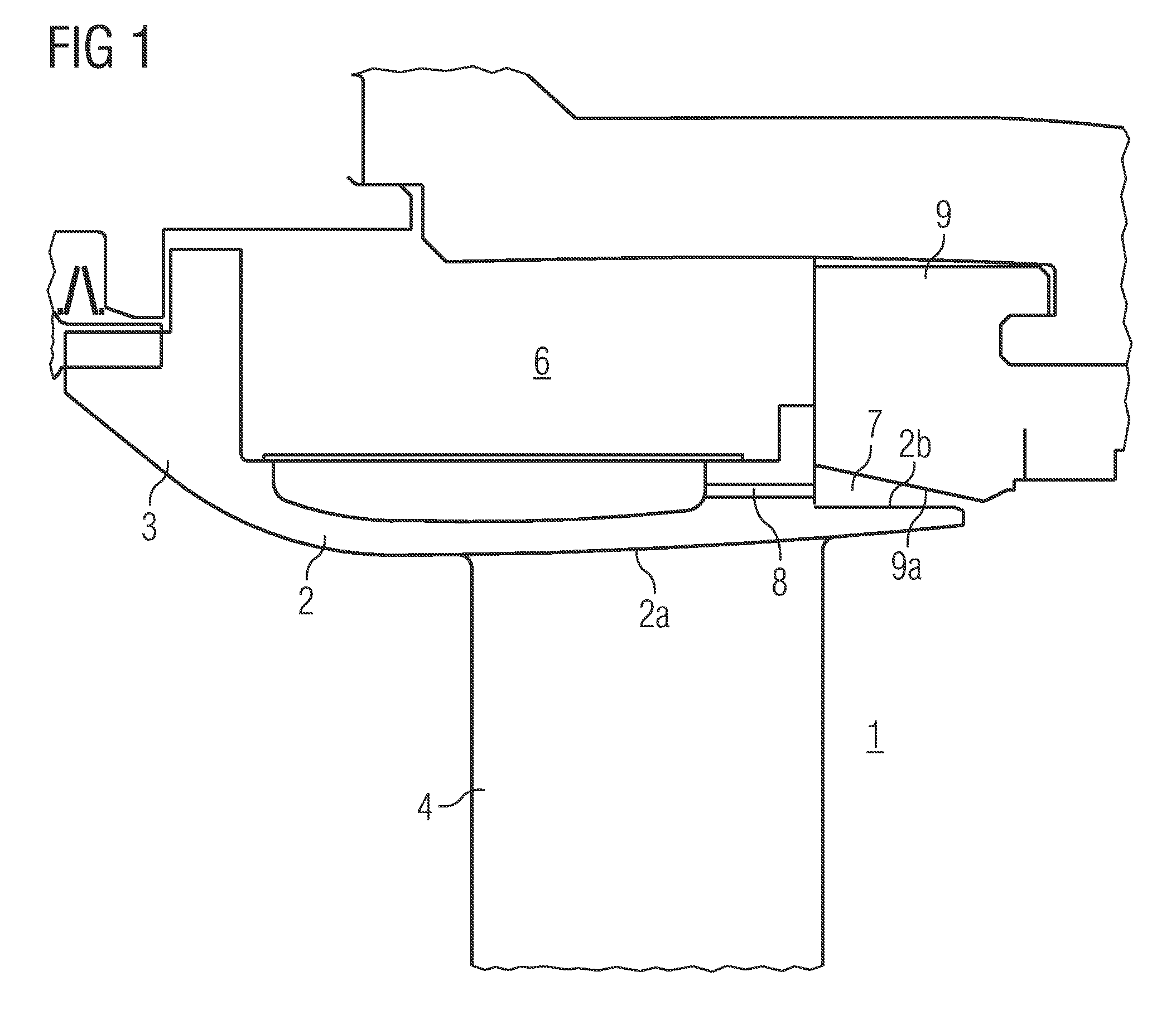
It has now been recognised that the cooling arrangement does not provide any significant heat transfer to the rear region of the wall 2, which means that the cooling of the rear region of the wall 2 will be insufficient or that a quantity of cool fluid to be supplied will be unacceptably high.

Method used


Image

  • Flow Machine
  • Flow Machine
  • Flow Machine

Examples


Embodiment Construction

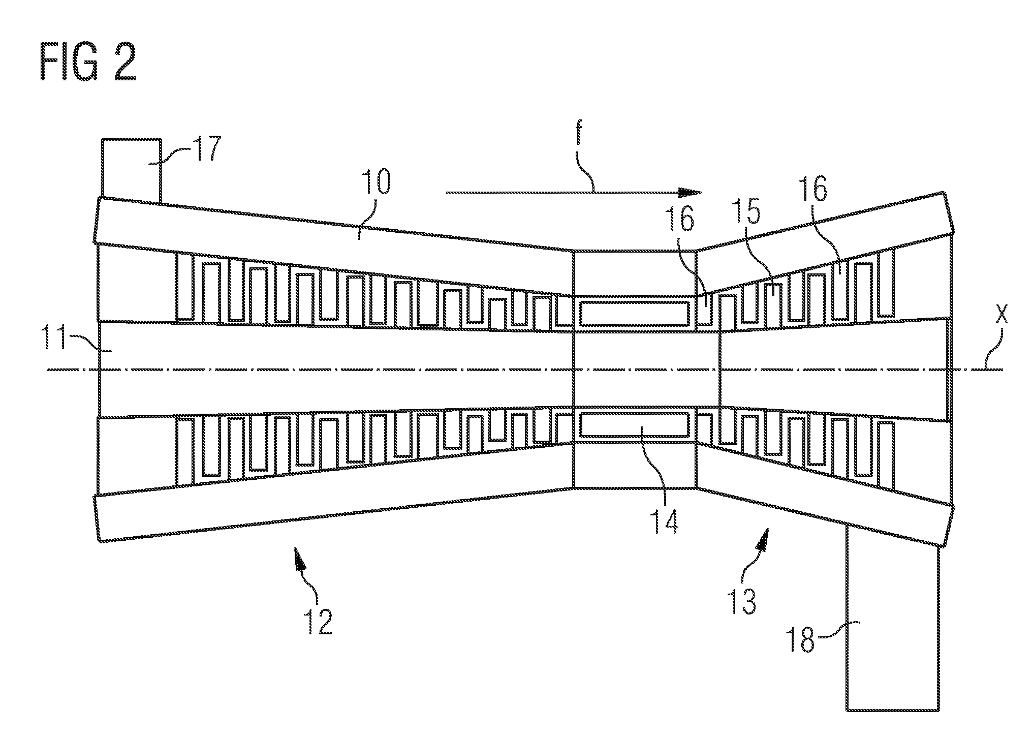
[0031]The present invention is now to be explained more closely with reference to FIGS. 2-7. FIG. 2 discloses a gas turbine engine. The present invention is advantageously applicable to such a gas turbine engine. Although the invention will be explained in connection with a gas turbine engine, it is to be noted that the invention is also applicable to other flow machines, for instance a turbocharger, a combustion chamber, a secondary combustion chamber, a rocket and the like.

[0032]The gas turbine engine has a stationary housing 10 and a rotor 11, which is rotatable in the housing 16 around a centre axis x. The gas turbine has a compressor part 12 and a turbine part 13. A combustion chamber arrangement 14 is, in a manner known per se, arranged between the compressor part 12 and the turbine part 13 for generating hot combustion gases. The turbine part 13 includes a number of rotor blades 15 mounted to the rotor 11 and a number of stationary guide vanes 16 mounted to the housing 10. A ...


PUM


Abstract

A flow machine is described having a first space adapted to contain a hot fluid and delimited by a wall. The wall having a first wall surface facing the first space and a second wall surface turned away from the first space. Cooling is provided for a region of the wall by supplying a relatively cool fluid onto the second wall surface. The cooling means includes a supply chamber containing the second fluid, a cavity adjacent the second wall surface, at least one duct, which has an inlet opening at the supply chamber and an outlet opening at the cavity for conveying the cool fluid to the cavity, and a deflection surface facing the cavity.

Description

CROSS REFERENCE TO RELATED APPLICATIONS[0001]This application is the US National Stage of International Application No. PCT / EP2006 / 063471, filed Jun. 22, 2006 and claims the benefit thereof. The International Application claims the benefits of British application No. 0513144.6 filed Jun. 28, 2005, both of the applications are incorporated by reference herein in their entirety.FIELD OF INVENTION[0002]The present invention refers generally to a flow machine, such as a gas turbine engine, a turbocharger, a combustion chamber, a secondary combustion chamber, a rocket and the like. More specifically, the present invention refers to a flow machine having a first space adapted to contain a first, relatively hot fluid and being delimited by means of a wall, which has a first wall surface facing the first space and a second wall surface turned away from the first space, the flow machine including cooling means for cooling a region of the wall by supplying a second, relatively cool fluid onto...

Claims


Application Information

Patent Timeline
Patent Type & Authority Applications(United States)
IPC IPC(8): F01D25/12F01D9/04
CPCF01D9/041F05D2260/201F05D2240/81
Inventor MALTSON, JOHN DAVID
Owner SIEMENS AG
Learn More