

System for recirculating the exhaust of a turbomachine
a turbomachine and exhaust gas technology, which is applied in the direction of machines/engines, mechanical apparatus, and non-fuel substance addition to fuel, etc., can solve the problems of internal turbomachine internal turbomachine corrosion, and internal components that are accelerated, corrosion and fouling
- Summary
- Abstract
- Description
- Claims
- Application Information
AI Technical Summary
Benefits of technology
Problems solved by technology
Method used
Image

Examples
second embodiment
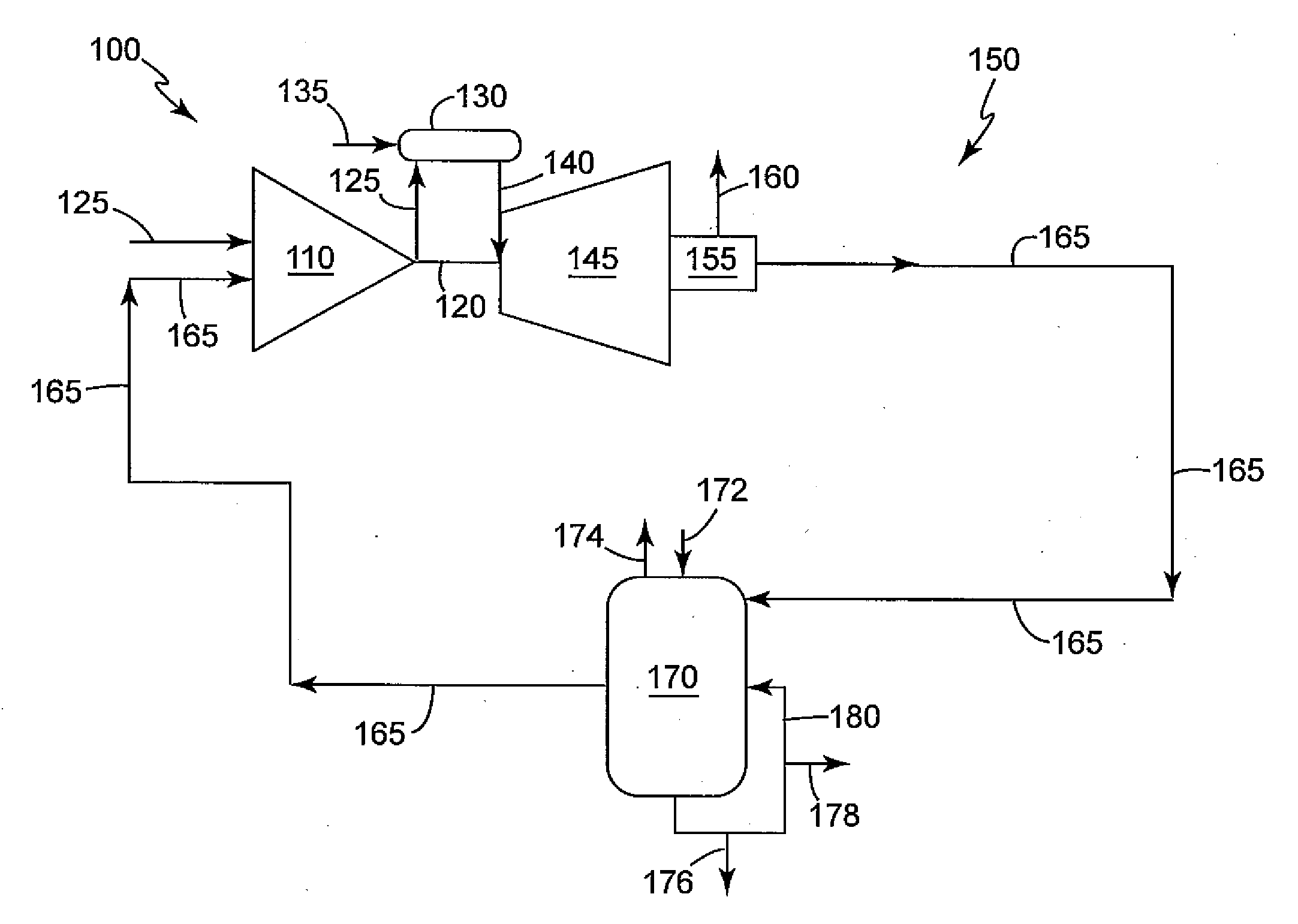
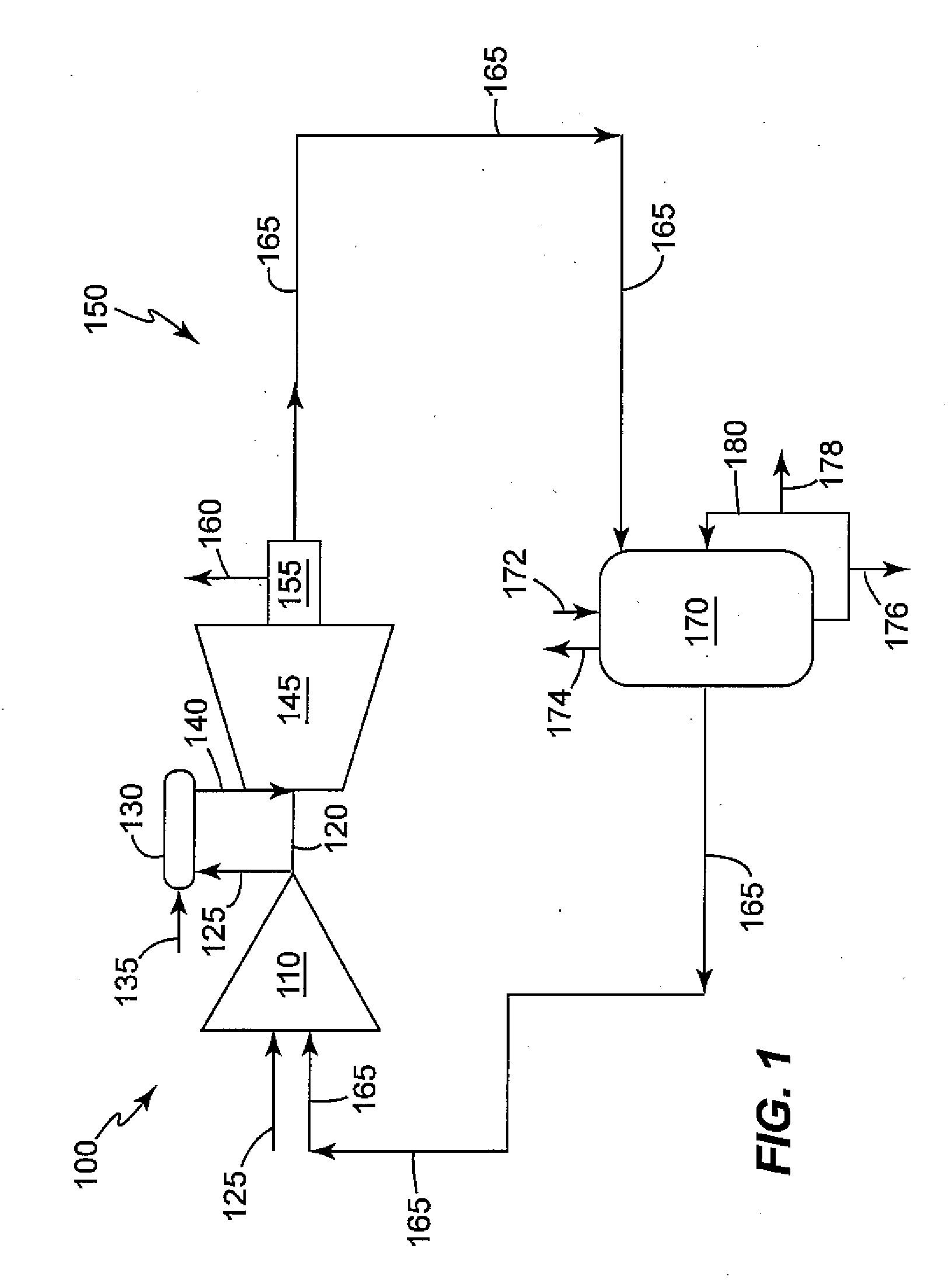
[0033]The at least one scrubber 170, in this second embodiment of the present scrubber 170, may reduce the temperature of the at least one exhaust stream 165 and may also remove a portion of the plurality of constituents (not illustrated) within the at least one exhaust stream 165, as described.
[0034]The at least one scrubber 170 may include at least one scrubber blow down line 176; and at least one scrubber recirculation line 180, as described. The at least one scrubber 170 may also include at least one scrubber make-up line 210 which may supply a fluid used in the scrubbing process.
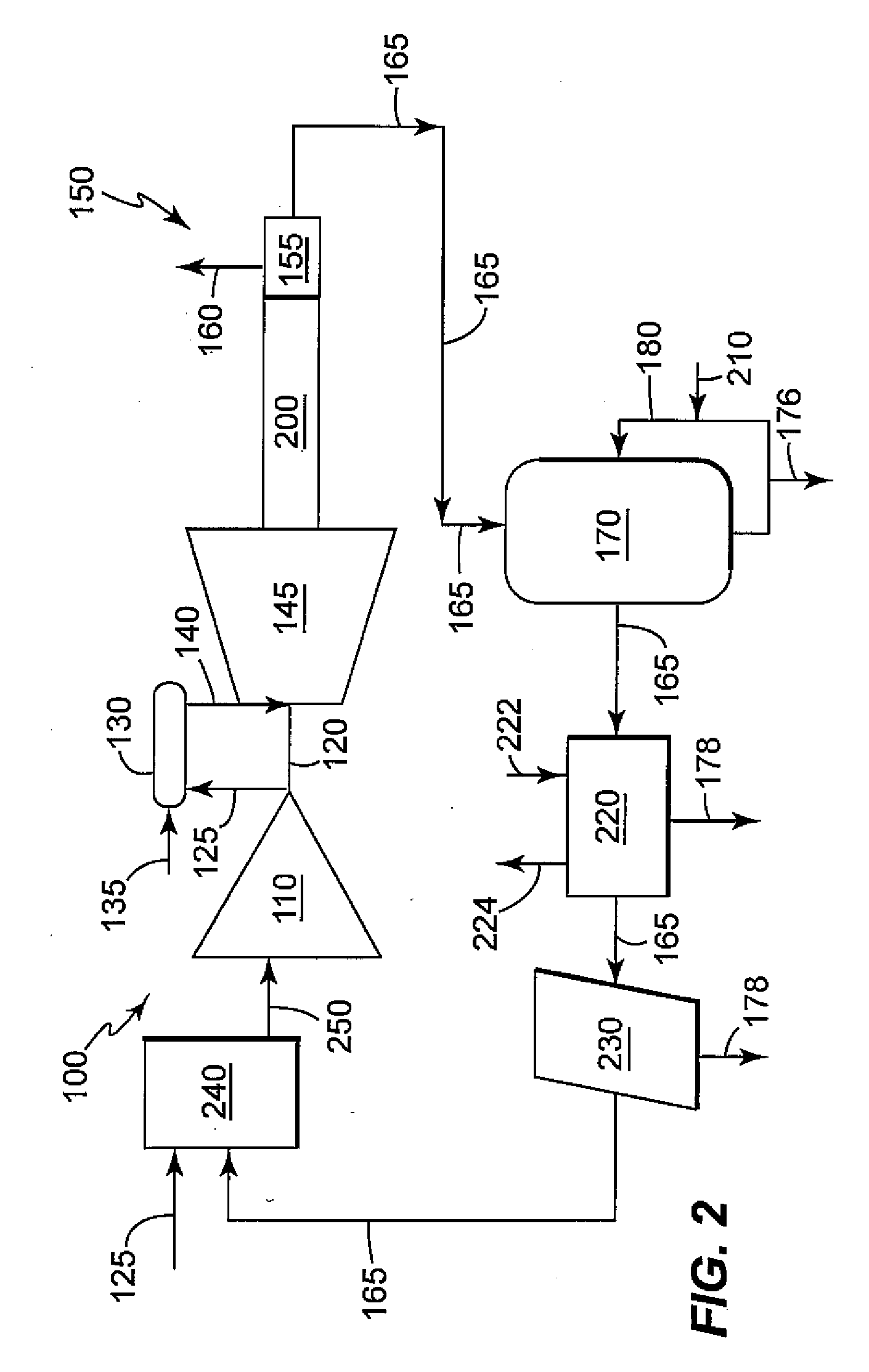
[0035]The at least one downstream heat exchanger 220 may be located downstream of the at least one scrubber 170 may cool the at least one exhaust stream 165 down to a reasonable temperature such that the performance of the gas turbine 100 may not be impacted due to a hot inlet air 130 temperature. For example, but not limiting of, the at least one downstream heat exchanger 220 may reduce the temperature...
third embodiment
[0048]In use, the exhaust gas recirculation system 150 of the present invention functions while the gas turbine 100 is in operation. The EGR flow modulation device 155 may be positioned to allow for the desired flowrate of the at least one exhaust stream 165, as previously described. The at least one exhaust stream 165 may then flow downstream through the at least one upstream heat exchanger 300, where a potion of condensable vapors of the at least one exhaust stream 165 may be removed via the condensable line 178.
[0049]Next, the at least one exhaust stream 165 may flow downstream through the at least one scrubber 170, as described above. Next, the at least one exhaust stream 165 may flow downstream of the at least one scrubber 170 to the at least one de-mister 230, and then into the at least one mixing station 240, all of which are described above. Downstream of the at least one mixing station 240, the inlet fluid 250 may flow into the compressor 110. The third embodiment of the pr...
fourth embodiment
[0052]the present invention may integrate the operation of the at least one upstream heat exchanger 300, at least one downstream heat exchanger 220, and at least one scrubber 170; to remove heat from, and thus lower the temperature of, the at least one exhaust stream 165 in stages, as described next.
[0053]In use, the exhaust gas recirculation system 150 of the fourth embodiment of the present invention functions while the gas turbine 100 is in operation. The EGR flow modulation device 155 may be positioned to allow for the desired flowrate of the at least one exhaust stream 165, as previously described. The at least one exhaust stream 165 may then flow downstream through the at least one upstream heat exchanger 300, which may lower the temperature of the at least one exhaust stream 165 to a range of about 120 degrees Fahrenheit to about 150 degrees Fahrenheit. Next, the at least one exhaust stream 165 may then flow downstream to the at least one scrubber 170, as described above. Nex...
PUM
 Abstract
Description
Claims
Application Information