Cooled cryostat radiation shield

a cryostat and radiation shield technology, applied in the field of cryostats, can solve the problems of difficult to obtain in some parts of the world, liquid helium is expensive, and the liquid liquid to boil

Active Publication Date: 2009-04-30
SIEMENS PLC
View PDF20 Cites 8 Cited by
  • Summary
  • Abstract
  • Description
  • Claims
  • Application Information

AI Technical Summary

Benefits of technology

[0016]An object of the present invention is to provide an improved cryostat that reduces consumption of cryogen during transportation, or at any time when active refrigeration is not present, and that does not suffer from the problems of the prior art.

Problems solved by technology

However, in the case of a helium cryogen, the hydrogen is solid during normal operation and will only be released as a gas if the cryogen vessel heats up to above about 20K.
A difficulty arises during transportation of the cryostat, when the refrigerator is switched off; or at any other time that the refrigerator 17 is inoperative.
With the refrigerator inoperative, any heat influx reaching the cryogen vessel, and any heat generated within the cryogen vessel, will cause cryogen liquid to boil.
Liquid helium is expensive, and difficult to obtain in some parts of the world.
Such cooling is a skilled process, and on-site cooling has been found to be very expensive.
Furthermore, the quantity of cryogen required to cool the equipment and cryostat from ambient temperature on arrival at an installation site has been found to far exceed current consumption rates over a reasonable transport time.
Known attempts to address this problem have met with difficulties.
This has been found somewhat effective in reducing thermal influx to the cryogen vessel, but has required increased size of OVC, and caused increased manufacturing costs.
Increased manufacturing costs also resulted from the additional assembly effort, and the material and labor costs of increasing the size of the OVC.

Method used


Image

  • Cooled cryostat radiation shield
  • Cooled cryostat radiation shield
  • Cooled cryostat radiation shield

Examples


Embodiment Construction

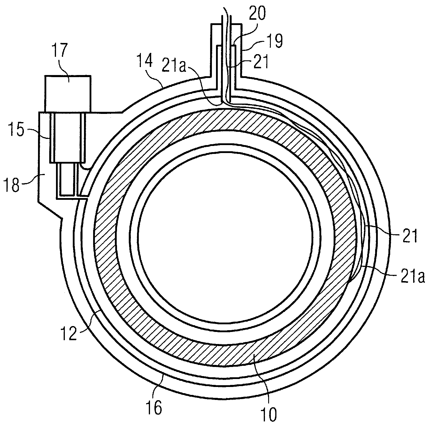
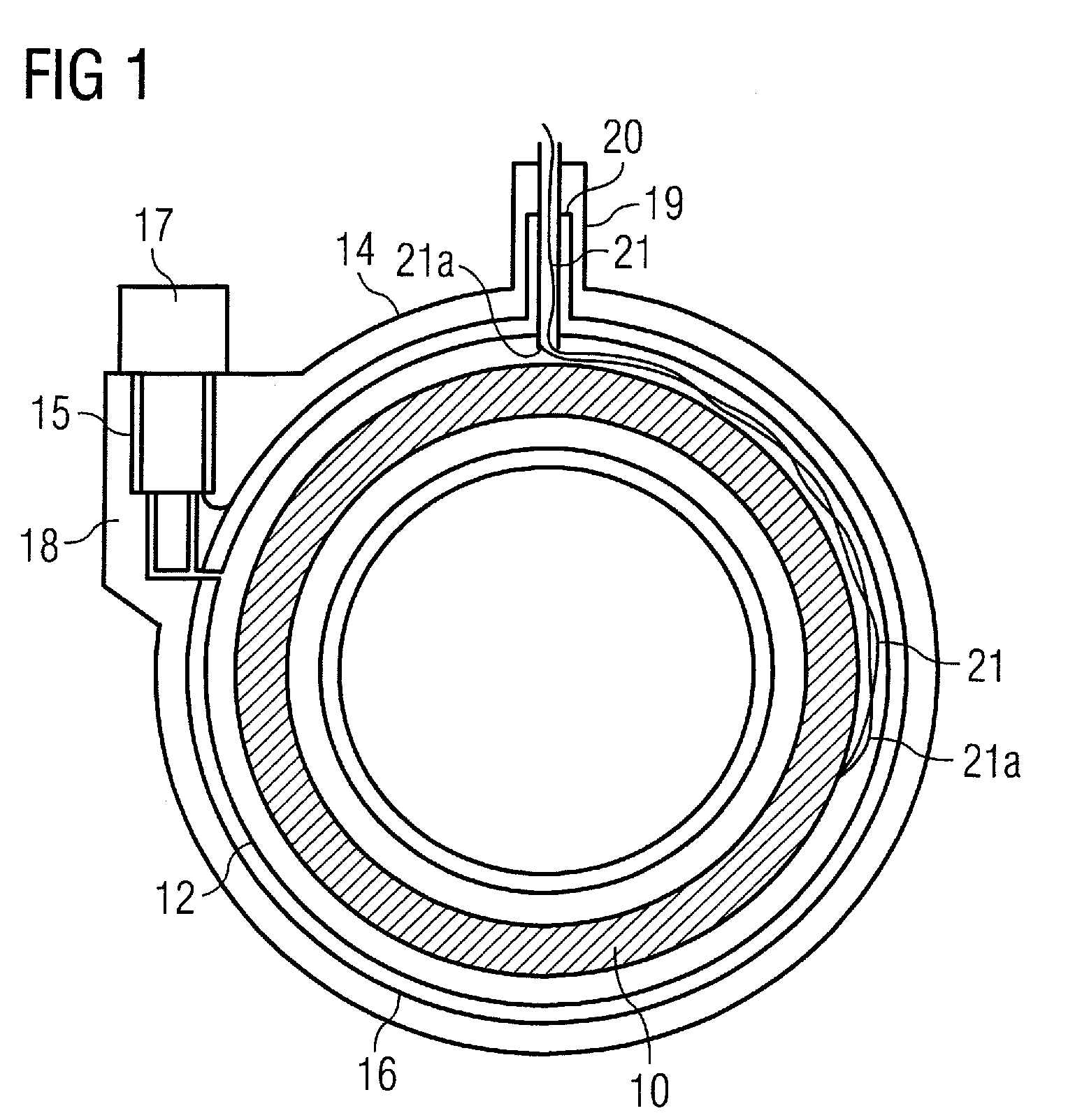
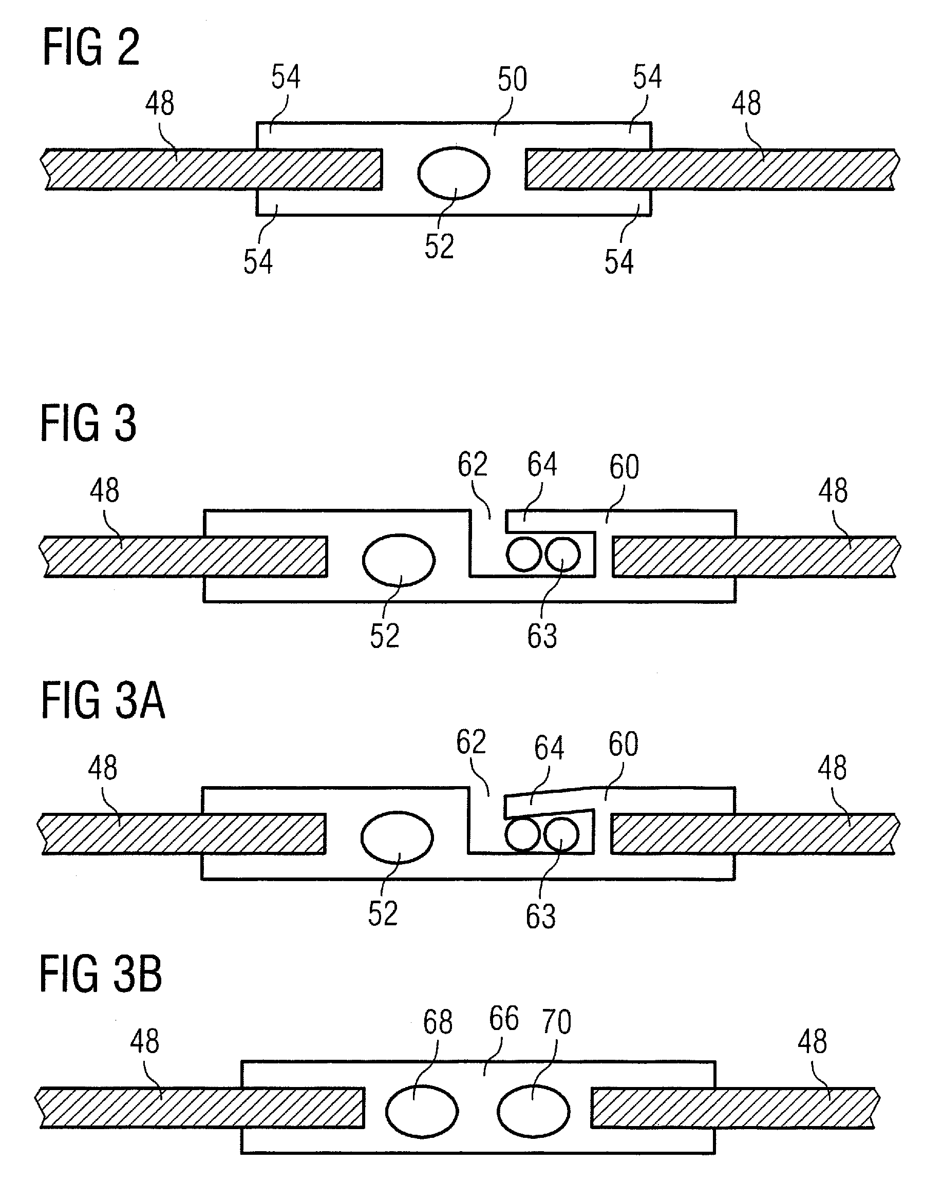
[0026]The present invention improves upon the cooled thermal radiation shield, as proposed in U.S. Pat. No. 7,170,377 and UK patent application GB 2 414 536. These prior art documents propose a cryogen-gas-carrying, thermally conductive tube wrapped around the outside of a thermal radiation shield. The thickness of the thermal radiation shield is effectively increased by the thickness of the tube, plus any fittings used to attach the tube to the thermal radiation shield. The increased effective thickness of the shield leads to increased overall dimension of the cryostat, including a larger OVC. In turn, this means a more costly system. Assembly is also complicated by the need to mount the cryogen-gas-carrying tube. The present invention aims to provide similar functionality but without increasing the thickness of the thermal radiation shield to such an extent; and to provide a simplified method of assembling a thermal radiation shield, by providing a thermally conductive conduit for...


PUM

PropertyMeasurementUnit
temperaturesaaaaaaaaaa
temperatureaaaaaaaaaa

Abstract

A cryostat has a cryogen vessel retained within an outer vacuum container, the cryogen vessel being provided with a vent path allowing cryogen gas to escape from the cryogen vessel, the cryostat further having a thermal radiation shield interposed between the cryogen vessel and the outer vacuum container. The vent path is arranged such that escaping cryogen gas is directed through a conduit, which forms an integral part of a thermal radiation shield.

Description

BACKGROUND OF THE INVENTION[0001]1. Field of the Invention[0002]The present invention relates to cryostats including cryogen vessels for retaining cooled equipment such as superconductive magnet coils. In particular, the present invention relates to radiation shields provided for reducing thermal radiation reaching a cryogen vessel from cryostat components which are at a higher temperature, and to venting arrangements allowing cryogen gas to escape from the cryogen vessel.[0003]2. Description of the Prior Art[0004]FIG. 1 shows a conventional arrangement of a cryostat including a cryogen vessel 12. A cooled superconducting magnet 10 is provided within cryogen vessel 12, itself retained within an outer vacuum chamber (OVC) 14. One or more thermal radiation shields 16 are provided in the vacuum space between the cryogen vessel 12 and the outer vacuum chamber 14. In some known arrangements, a refrigerator 17 is mounted in a refrigerator sock 15 located in a turret 18 provided for the pu...

Claims


Application Information

Patent Timeline
Patent Type & Authority Applications(United States)
IPC IPC(8): F17C3/04F17C3/08F17C13/00F16L9/02F16L59/08B21D43/02
CPCF17C3/085Y10T29/4935G01R33/3804F17C2203/0687F17C2221/017F17C2270/0536
Inventor CLAYTON, NICHOLAS JOHNGOWLAND, RICHARDRAYNER, EDGAR CHARLES MALCOLM
Owner SIEMENS PLC
Why Eureka
Try Eureka