Shielded Conductor for Vehicle

Inactive Publication Date: 2009-04-30
AUTONETWORKS TECH LTD +2
View PDF13 Cites 26 Cited by
  • Summary
  • Abstract
  • Description
  • Claims
  • Application Information

AI Technical Summary

Benefits of technology

[0008]The absorbed electromagnetic wave energy P, as is understood from the above approximate expression, is proportional to the amount of a magnetic loss (ωμ″H2), while the magnetic loss is proportional to a frequency f and the magnitude of a complex permeability μ. It is generally said that the absolute value of the complex permeability of iron is approximately 1000, which allows iron to perform higher shielding effect. Iron, however, is easy to rust and inferior in corrosion resistivity

Problems solved by technology

The stainless steel pipe, however, is inferior in the shielding property, for example, in a high frequency bandwidth higher than 1

Method used


Image

  • Shielded Conductor for Vehicle
  • Shielded Conductor for Vehicle
  • Shielded Conductor for Vehicle

Examples


first embodiment

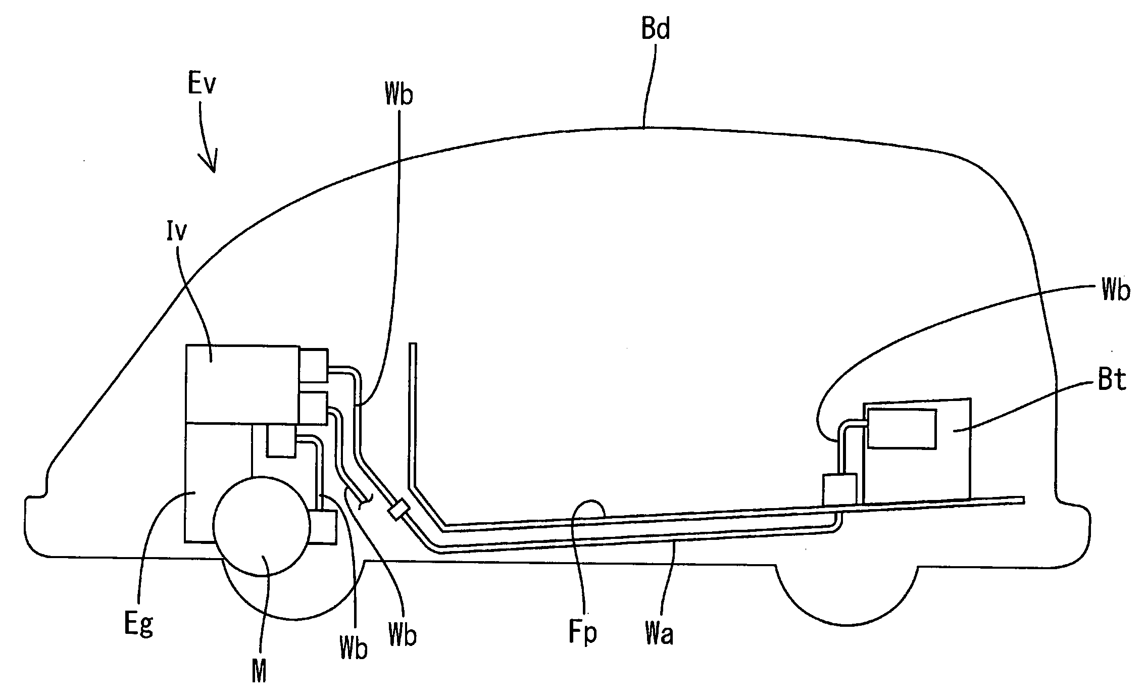
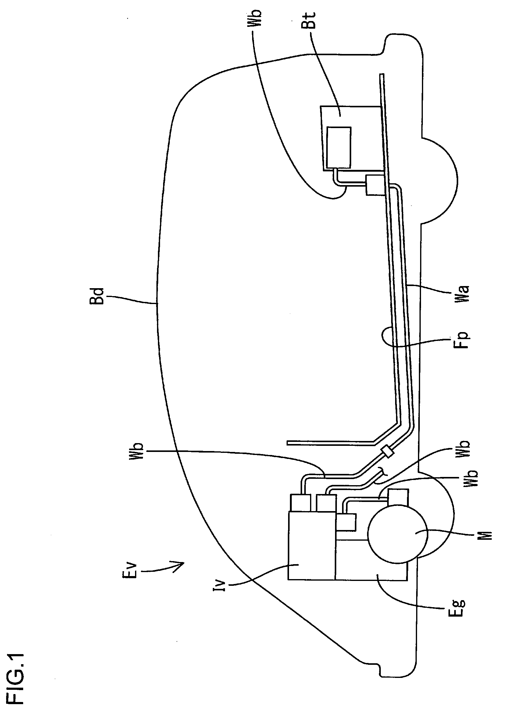
[0023]A first embodiment according to the present invention will be explained with reference to FIGS. 1 through 5. An electric vehicle EV has a body Bd and an engine room in a front portion of the body Bd. An inverter Iv configuring a motor driving circuit and a gasoline engine Eg are accommodated in the engine room. A battery Bt configuring a motor circuit is mounted in a rear portion of the body Bd. A motor M for running front wheels is disposed below the engine room, while another motor (not illustrated) for running rear wheels is disposed in the rear portion of the body Bd. A shielded conductor Wa and an interior conducting path Wb are conductively connected between the inverter Iv and the Battery Bt, while another interior conducting path Wb is conductively connected between the inverter Iv and the motor M for running the front wheels, and another shielded conductor Wa and the other interior conducting path are conductively connected between the inverter Iv and the motor for ru...

second embodiment

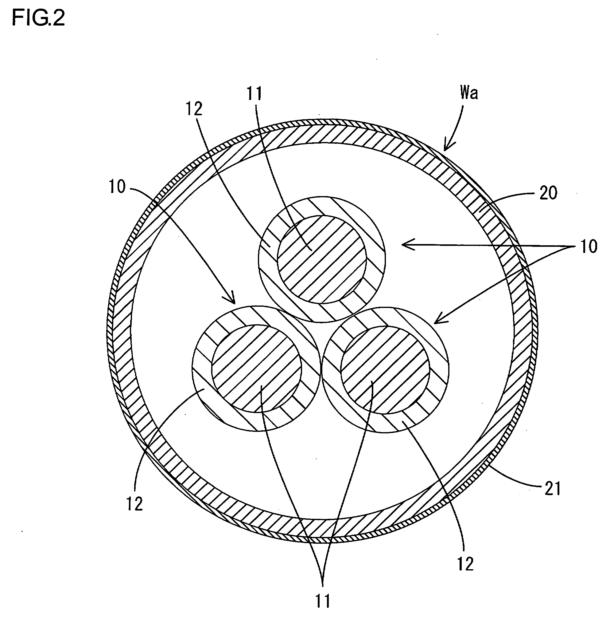
[0032]A second embodiment will be explained with reference to FIG. 7. Constructions similar to the first embodiment are designated by the same numerals, therefore the explanations are omitted. The shielded conductor Wa of the present embodiment has the metal pipe 20 made of stainless steel and having an inner surface 25, the unshielded wires 10, and a resin layer 30. The resin layer 30 is formed between each of the unshielded wires 10 and the inner peripheral surface 25 of the metal pipe 20 through the entire length of the metal pipe 20. The resin layer 30 is formed by filling a clearance between the unshielded wires 10 each and the inner peripheral surface 25 of the metal pipe 20 with, for example, two-component urethane resin of HDI type containing ferrite powder. Heat radiated from the each unshielded wire 10 is transferred through the periphery of each insulating layer 12 and the resin layer 30 to the inner peripheral surface 25 of the metal pipe 20 and dissipated from the outer...


PUM


Abstract

A shield conductor has a metal pipe and wires accommodated in the metal pipe. The metal pipe is stainless steel, and the stainless steel pipe is provided with a resin layer containing a magnetic material.

Description

TECHNICAL FIELD[0001]The present invention relates to a shielded conductor for a vehicle to be mounted on an electric vehicle.BACKGROUND ART[0002]One example of a known shielded conductor of this type is a shielded conductor that has a plurality of unshielded wires and a pipe for accommodating the wires to protect them as well as for functioning as an electromagnetic shielding layer (Patent Document 1). One pipe considered to be used as a shielded conductor of this type is made of stainless steel, which is superior in corrosion resistivity.[Patent Document 1] Japanese Unexamined Patent Application Publication 2004-171952[0003]The stainless steel pipe, however, is inferior in the shielding property, for example, in a high frequency bandwidth higher than 100 MHz. The shielded conductor therefore cannot provide a sufficient shielding effect in the high frequency bandwidth in some cases.[0004]The present invention was achieved in accordance with the circumstances as described above, and...

Claims


Application Information

Patent Timeline
IPC IPC(8): H01B9/02
CPCH01B7/16H01B7/1895B60L2270/147B60L11/1803Y02T10/7005H01B9/02B60L50/51Y02T10/70
Inventor WATANABE, KUNIHIKO
Owner AUTONETWORKS TECH LTD
Why Eureka
Try Eureka