Treatment process and system for wastewater, process waters, and produced waters applications

Inactive Publication Date: 2009-04-30
ITS ENGINEERED SYST
View PDF10 Cites 83 Cited by
  • Summary
  • Abstract
  • Description
  • Claims
  • Application Information

AI Technical Summary

Benefits of technology

[0019]The method for the removal of contaminants from a contaminated water stream may further comprise providing instrumentation for the monitoring and automatic control of the at least one electrocoagulation cell. The method for the removal of contaminants from a contaminated water stream may comprise providing instrumentation for control of at least one operational parameter selected from the group consisting of: automated DC voltage control, polarity reversal of the electrodes in the at least one electrocoagulation cell, recirculation of the process liquid, initiation and control of cleaning cycles, control of inlet feed flow rate, and combinations thereof. The method for the removal of contaminants from a contaminated water stream may com

Problems solved by technology

Contaminated water sources being considered for treatment and purification present unique challenges which must be considered in the design of water treatment processes.
Combinations of conventional water treatment processes which have been evaluated for these more difficult treatment applications have resulted in degrees of success ranging from failure to marginal acceptability in efficiency and economical operation.
In most cases, technical difficultie

Method used


Image

  • Treatment process and system for wastewater, process waters, and produced waters applications
  • Treatment process and system for wastewater, process waters, and produced waters applications
  • Treatment process and system for wastewater, process waters, and produced waters applications

Examples


example 1

Example 1

20 GPM Feed Water Treatment Pilot Plant

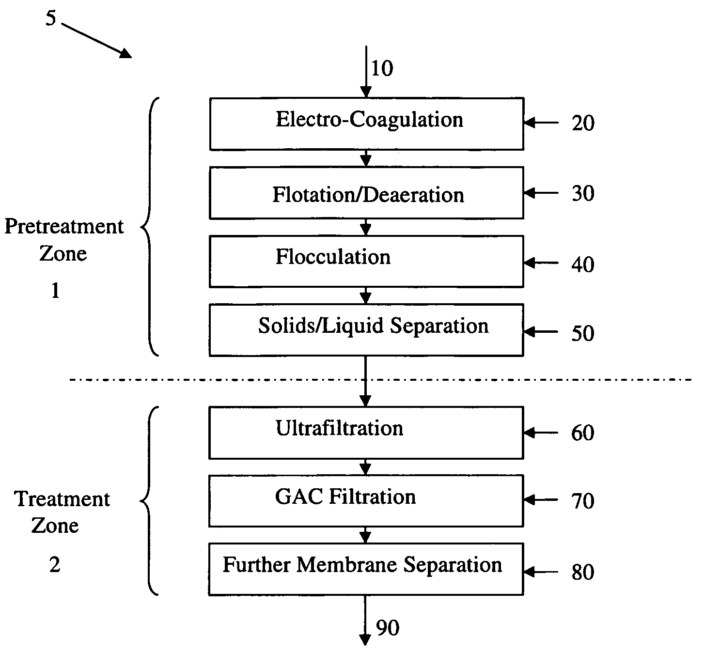
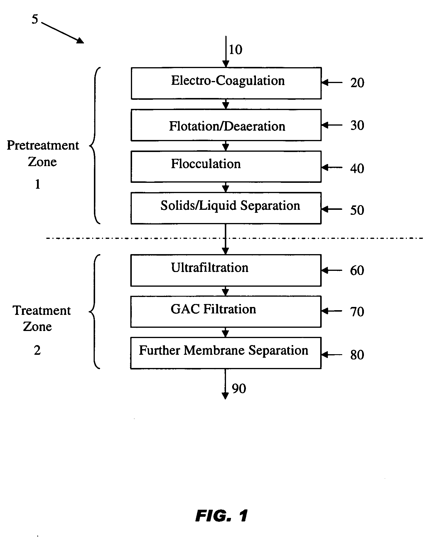
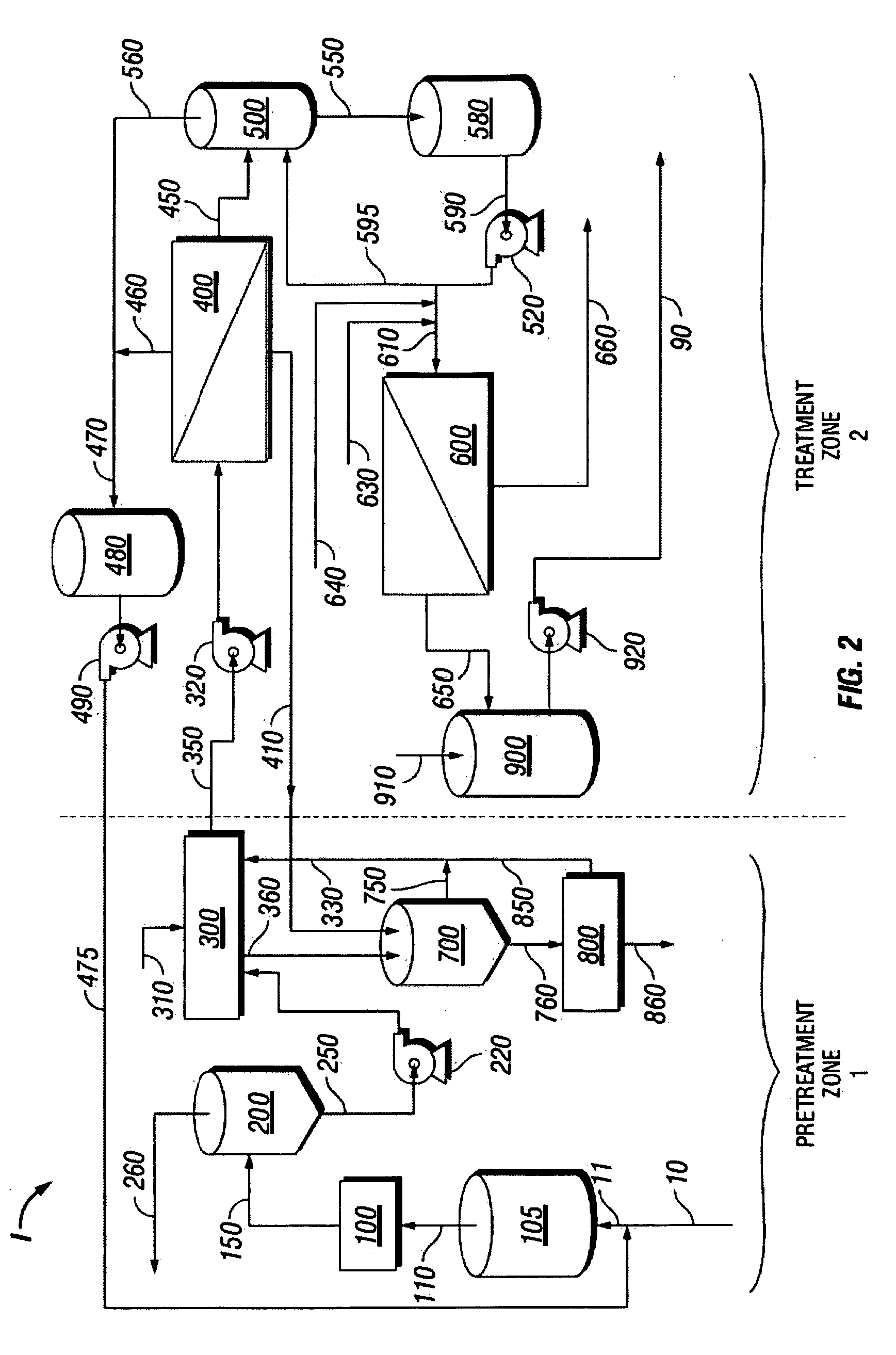
[0096]A water treatment system in accordance with the present disclosure was designed with a 20 GPM feed produced water stream 10. Description of the water treatment pilot plant II will now be made with reference to FIGS. 6, 7 and 8. Feed water stream 10 at 20-21 GPM and backwash recycle stream 475 at about 2 GPM enter strainer 105 via inlet feed stream 11. Strainer outlet stream 110 enters EC system 100. In this embodiment of EC system 100, the EC system comprises two electro-coagulation cells 101 and 102. EC system exit stream 150 at a flow rate of about 21.5 GPM is sent to CRV 200.

[0097]A more detailed flow diagram of CRV 200 operation, sludge handling and waste recycle of pretreatment zone 1 of the pilot plant is presented in FIG. 5. In this embodiment, CRV 200 comprises 20 gallon HDPE tank and impeller 205. Retention in CRV 200 is greater than 5 minutes to allow for deaeration, completion of coagulation, and flotation. CRV exit sl...


PUM

PropertyMeasurementUnit
Fractionaaaaaaaaaa
Percent by volumeaaaaaaaaaa
Temperatureaaaaaaaaaa

Abstract

A method for the removal of contaminants from a contaminated water stream, by pretreating the contaminated water stream to yield a pretreated water stream, wherein pretreating comprises passing the contaminated water stream to at least one electrocoagulation cell wherein coagulation of contaminants is promoted, yielding an electrocoagulated stream; and separating coagulated contaminants from the electrocoagulated stream.
An electrocoagulation reactor comprising a plurality of electrodes positioned parallel to each other and provided with a means of energizing each electrode; a fluid inlet for an inlet stream comprising contaminated water; a fluid outlet for an outlet stream comprising electrocoagulated products; a flow distributor system; and a gas distribution system for injecting a gas into the electrocoagulation reactor. An electrocoagulation system for treating a contaminated water stream, the system comprising at least one electrocoagulation reactor.

Description

CROSS-REFERENCE TO RELATED APPLICATIONS[0001]This application claims the benefit under 35 U.S.C. § 119(e) of U.S. Provisional Patent Application Nos. 60 / 894,328 filed Mar. 12, 2007, and entitled, “Treatment Process and System for Wastewater, Process Waters, and Produced Waters Applications.”STATEMENT REGARDING FEDERALLY SPONSORED RESEARCH OR DEVELOPMENT[0002]Not applicable.BACKGROUND OF THE INVENTION[0003]1. Field of the Invention[0004]This disclosure relates to water treatment systems and to processes for removing contaminants from contaminated water streams. More particularly, the disclosure relates to water treatment systems and processes in which electrocoagulation and associated systems are used in place of chemical treatment systems in a pretreatment zone prior to membrane separation systems of the treatment zone.[0005]2. Background of the Invention[0006]Contaminated water sources being considered for treatment and purification present unique challenges which must be considere...

Claims


Application Information

Patent Timeline
IPC IPC(8): C02F1/44C02F1/463C02F1/24C02F103/00B01D65/02
CPCC02F1/20C02F1/24C02F1/283C02F1/441C02F1/444C02F1/463C02F2209/11C02F9/00C02F2209/02C02F2209/04C02F2209/05C02F2209/06C02F1/56
Inventor SKINNER, HARRY O.GRIMME, GREGORY L.
Owner ITS ENGINEERED SYST
Why Eureka
Try Eureka