Antenna calibration method and system

a phased array radar and antenna calibration technology, applied in wave based measurement systems, resonant antennas, instruments, etc., can solve the problems of corrupting techniques, unable to recalibrate antenna elements that are beyond the test manifold coupler, and inability to calibrate powerful calibration capabilities

Inactive Publication Date: 2008-08-05
THE UNITED STATES OF AMERICA AS REPRESENTED BY THE SECRETARY OF THE NAVY
View PDF13 Cites 235 Cited by
  • Summary
  • Abstract
  • Description
  • Claims
  • Application Information

AI Technical Summary

Benefits of technology

[0016]Another advantage is that the system is compact and inexpensive.

Problems solved by technology

Unfortunately, the physical size and weight of these scanners and the associated mechanical support structure needed to perform this level of calibration makes a scanner type structure unmanageable to be used for in-situ type measurements
Although the system permits recalibration using a known far-field source, it cannot recalibrate antenna elements that are beyond the test manifold coupler.
These techniques, which provide a powerful calibration capability, become corrupt if the elements themselves become defective.

Method used


Image

  • Antenna calibration method and system
  • Antenna calibration method and system
  • Antenna calibration method and system

Examples


Embodiment Construction

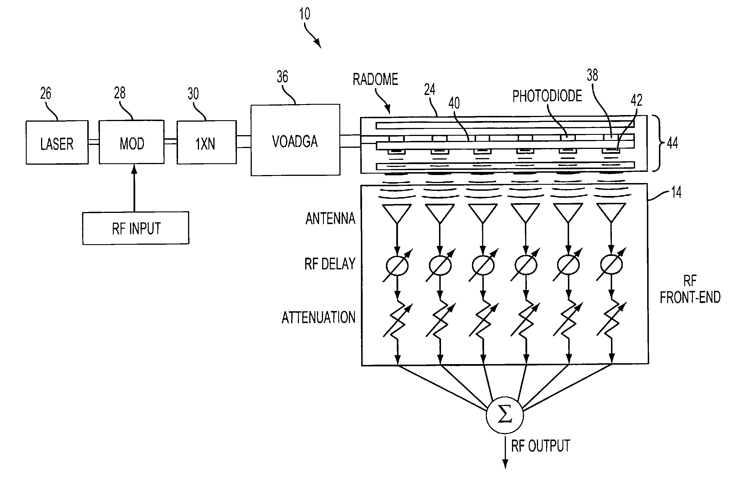
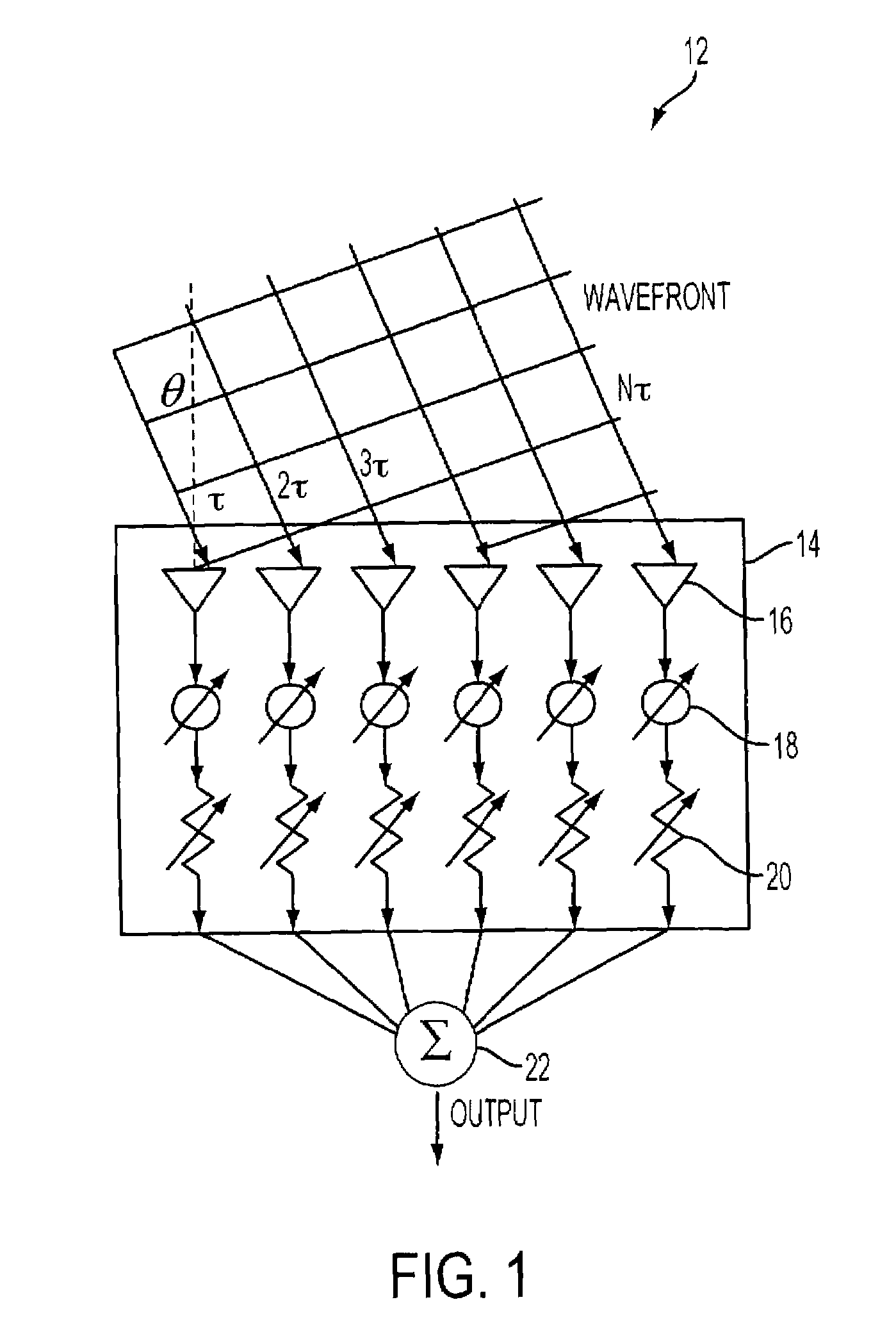
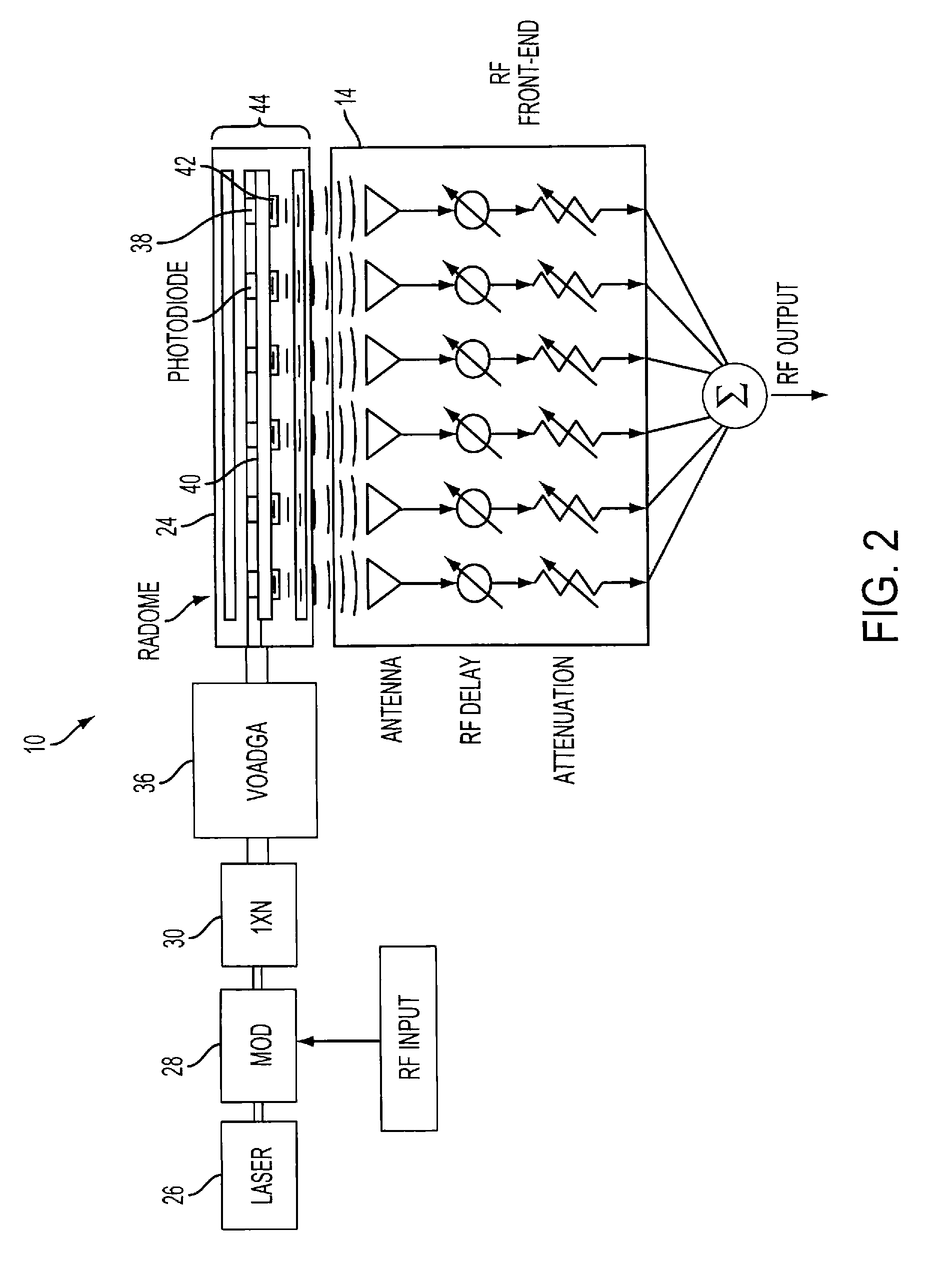
[0032]FIG. 1 illustrates the desired characteristics of an in-situ optical calibrator 10 (see also FIG. 2) in a phased array antenna 12. The calibrator should distribute a: modulated RF signal over the aperture of an RF front-end 14, with an adjustable relative time delay, τ, between adjacent antenna elements 16, each connected to an adjustable phase shifter 18 and an adjustable attenuator 20 with outputs combined in a summer 22. For example, consider a system with a 24×24 element array antenna, an RF frequency range from 4 to 20 GHz and beam steering angles from −45° to 45° along the azimuth and elevation directions. The required delay resolution should be less than 1% of the period, which becomes 0.5 ps for the 20 GHz signal.

[0033]FIG. 2 illustrates optical calibrator 10 embedded inside a radome 24. Light from a laser 26 is modulated by an optical intensity modulator 28 at RF input signal and is split into N fiber channels by a 1×N splitter 30, where N is the number of antenna ele...


PUM


Abstract

A phased array antenna system includes an RF front end, a radome, and an optical calibrator embedded in the radome for enabling in-situ calibration of the RF front end. The optical calibrator employs an optical timing signal generator (OTSG), a Variable Optical Amplitude and Delay Generator array (VOADGA) for receiving the modulated optical output signal and generating a plurality of VOADGA timing signals, and an optical timing signal distributor (OTSD). The in-situ optical calibrator allows for reduced calibration time and makes it feasible to perform calibration whenever necessary.

Description

CROSS-REFERENCE TO RELATED APPLICATIONS[0001]This Application is a Non-Prov of Prov (35 USC 119(e)) application 60 / 662,342 filed on Mar. 15, 2005, incorporated herein by reference.TECHNICAL FIELD[0002]The present invention is directed to a method and system for calibrating a phased array radar system. More particularly, the invention is directed to an in-situ optical phased array radar calibration method and system.BACKGROUND OF THE INVENTION[0003]A phased array antenna in an array of antenna elements connected together that are switched between transmit and receive channels. Steering is accomplished by controlling the phase and amplitude of the elements. It is also necessary to adjust the phase and amplitude in order to correct or compensate for errors and inaccuracies due to environmental and other conditions. In order to make the desired adjustments, it is necessary to calibrate and tune the antenna system. The ability for a multi-element array antenna system to electronically fo...

Claims


Application Information

Patent Timeline
Patent Type & Authority Patents(United States)
IPC IPC(8): H01Q3/00G01S1/44H01Q3/22
CPCH01Q1/405H01Q3/267H01Q3/2676H01Q15/0053H01Q9/26H01Q21/061H01Q7/00
Inventor PAEK, EUNG GIPARENT, MARKCHOE, JOON Y
Owner THE UNITED STATES OF AMERICA AS REPRESENTED BY THE SECRETARY OF THE NAVY
Why Eureka
Try Eureka