Flow distributor and baffle system for a falling film evaporator

Active Publication Date: 2005-03-22
TRANE INT INC
View PDF15 Cites 234 Cited by
  • Summary
  • Abstract
  • Description
  • Claims
  • Application Information

AI Technical Summary

Benefits of technology

One or more of these and/or other objects of the invention are achieved by providing a falling film evaporator with a flow distributor that comprises a stack of at least three perforated plates each of which are separated by nearly full-width, full-length gaps. The flow distributor may also include

Problems solved by technology

More recently, environmental, efficiency and other similar issues and concerns have resulted in a need to re-think evaporator design in refrigeration chillers in view of making such evaporators more efficient from a heat exchange efficiency standpoint and in view of reducing the size of the refrigerant charge needed in such chillers.
Those issues and the ramifications thereof have driven both a need to reduce the amount and change the nature of the refrigerant used in refrigeration chillers.
While the use and application of evaporators of a falling film design in refrigeration chillers is theoretically beneficial, their design, manufacture and incorporation into chiller systems has proven challenging, particularly with respect to the need to uniformly distribute refrigerant across the tube bundles therein.
The separate vapor-liquid separator component in the RTHC

Method used


Image

  • Flow distributor and baffle system for a falling film evaporator
  • Flow distributor and baffle system for a falling film evaporator
  • Flow distributor and baffle system for a falling film evaporator

Examples


Embodiment Construction

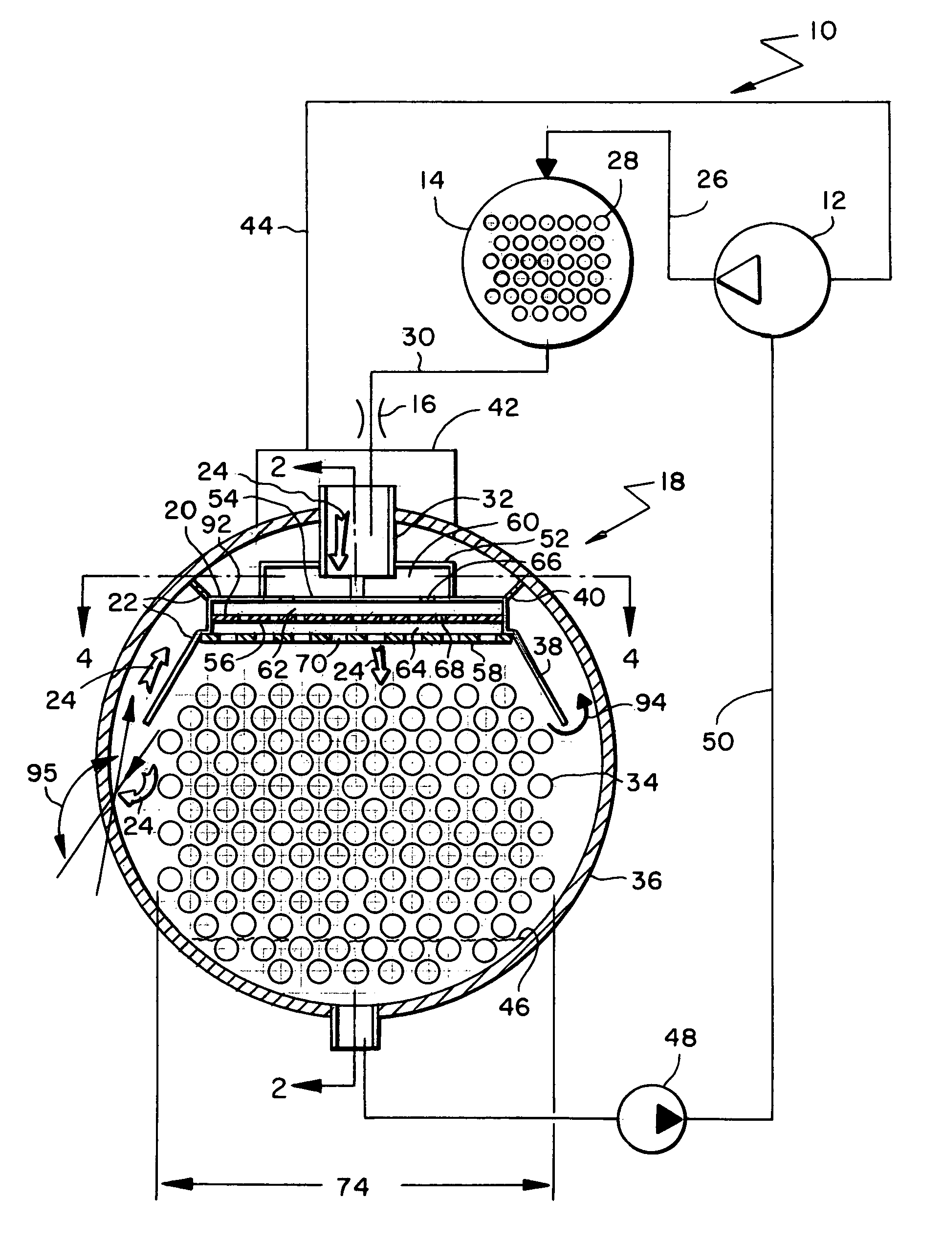
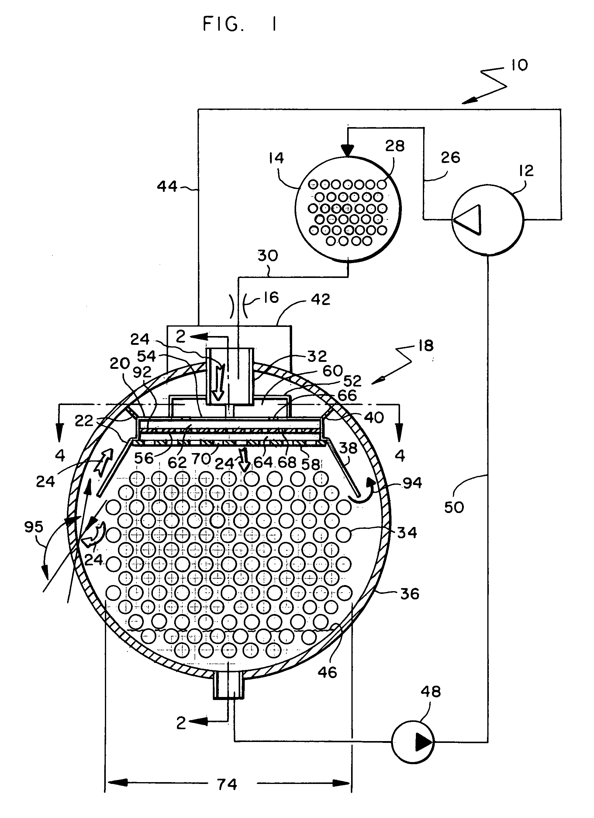
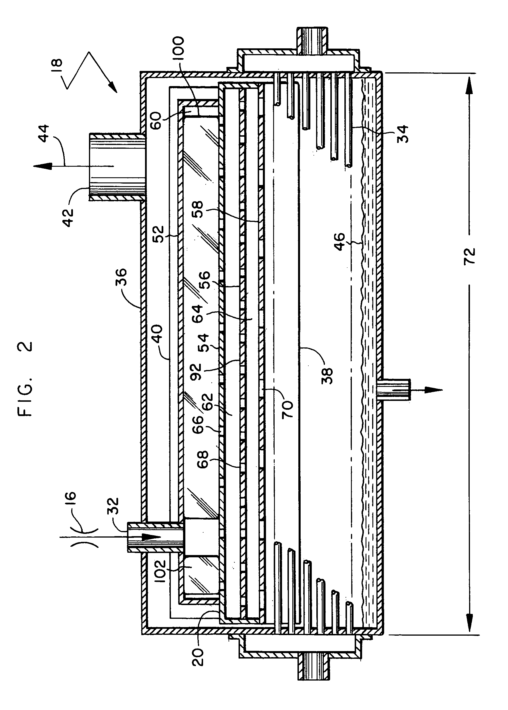
FIG. 1 is a partially schematic view of a refrigerant chiller system 10 whose primary components include a compressor 12, a condenser 14, an expansion device 16 and a falling film evaporator 18. Compressor 12 can be any type of compressor including, but not limited to, a centrifugal, screw, scroll or reciprocating. Evaporator 18 includes a distributor 20 and a baffle system 22 that help determine the flow pattern of a two-phase refrigerant 24 flowing through the evaporator. The main components of chiller system 10 are interconnected to create a conventional closed-loop refrigerant circuit for providing chilled water.

In basic operation, compressor 12 discharges compressed gaseous refrigerant through a discharge line 26 to condenser 14. A cooling fluid passing through a tube bundle 28 in condenser 14 cools and condenses the refrigerant. A line 30 conveys the condensed refrigerant from condenser 14 to expansion device 16. Expansion device 16 is any flow restriction such as a orifice pl...


PUM


Abstract

A falling film evaporator includes a flow distributor for uniformly distributing a two-phase refrigerant mixture across a tube bundle. The flow distributor includes a stack of at least three perforated plates each of which are separated by nearly full-width, full-length gaps or chambers. The flow distributor may also include a suction baffle and/or a distributor baffle. The distributor baffle extends downward to provide a hairpin turn past which refrigerant travels before exiting the evaporator. This directional change helps separate liquid from a primarily gaseous refrigerant stream. The suction baffle has various size openings to ensure that the flow rate of refrigerant through the hairpin turn is generally uniform and is maintained low enough to ensure liquid disentrainment over and along the length of the tube bundle within the evaporator.

Description

BACKGROUND OF THE INVENTION 1. Field of the Invention The present invention relates to a falling film evaporator of a refrigerant system. More particularly, the present invention relates to a distributor and baffle system that directs the flow of a two-phase refrigerant mixture entering and vapor leaving the evaporator. 2. Description of Related Art The primary components of a refrigeration chiller include a compressor, a condenser, an expansion device and an evaporator. Higher pressure refrigerant gas is delivered from the compressor to the condenser where the refrigerant gas is cooled and condensed to the liquid state. The condensed refrigerant passes from the condenser to and through the expansion device. Passage of the refrigerant through the expansion device causes a pressure drop therein and the further cooling thereof. As a result, the refrigerant delivered from the expansion device to the evaporator is a relatively cool, saturated two-phase mixture. The two-phase refrigerant...

Claims


Application Information

Patent Timeline
IPC IPC(8): F28F27/00F28F27/02F25B39/02
CPCF25B39/028F28F9/0278F28D21/0017F25B2339/0242
Inventor DINGEL, BENJAMIN E.LARSON, JAMES W.
Owner TRANE INT INC
Why Eureka
Try Eureka