Temperature Adjustment Method
- Summary
- Abstract
- Description
- Claims
- Application Information
AI Technical Summary
Benefits of technology
Problems solved by technology
Method used
Image
Examples
first embodiment
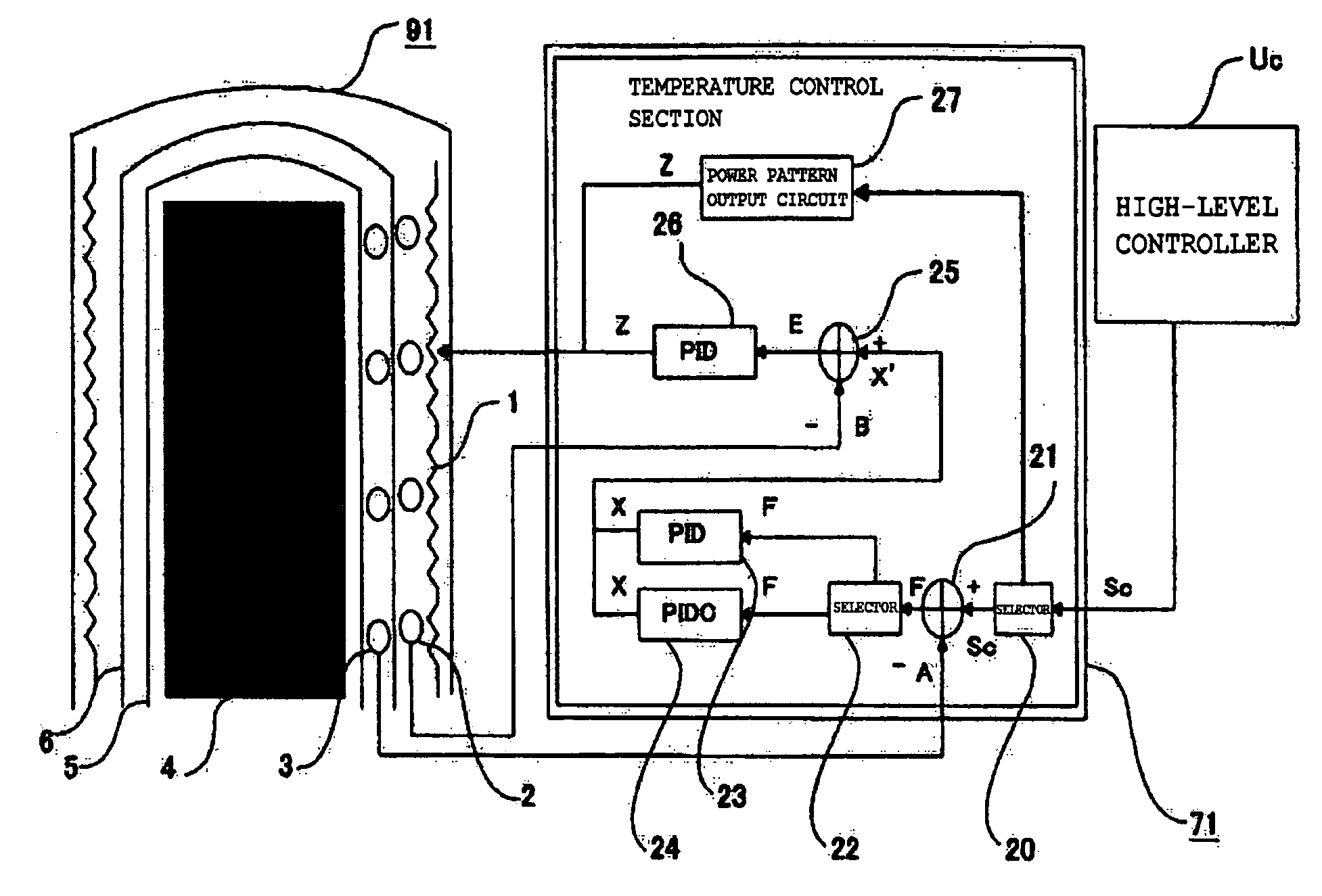
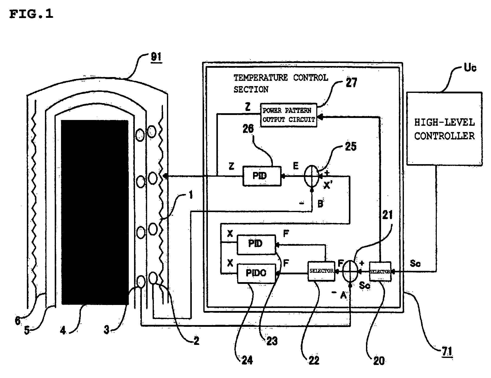
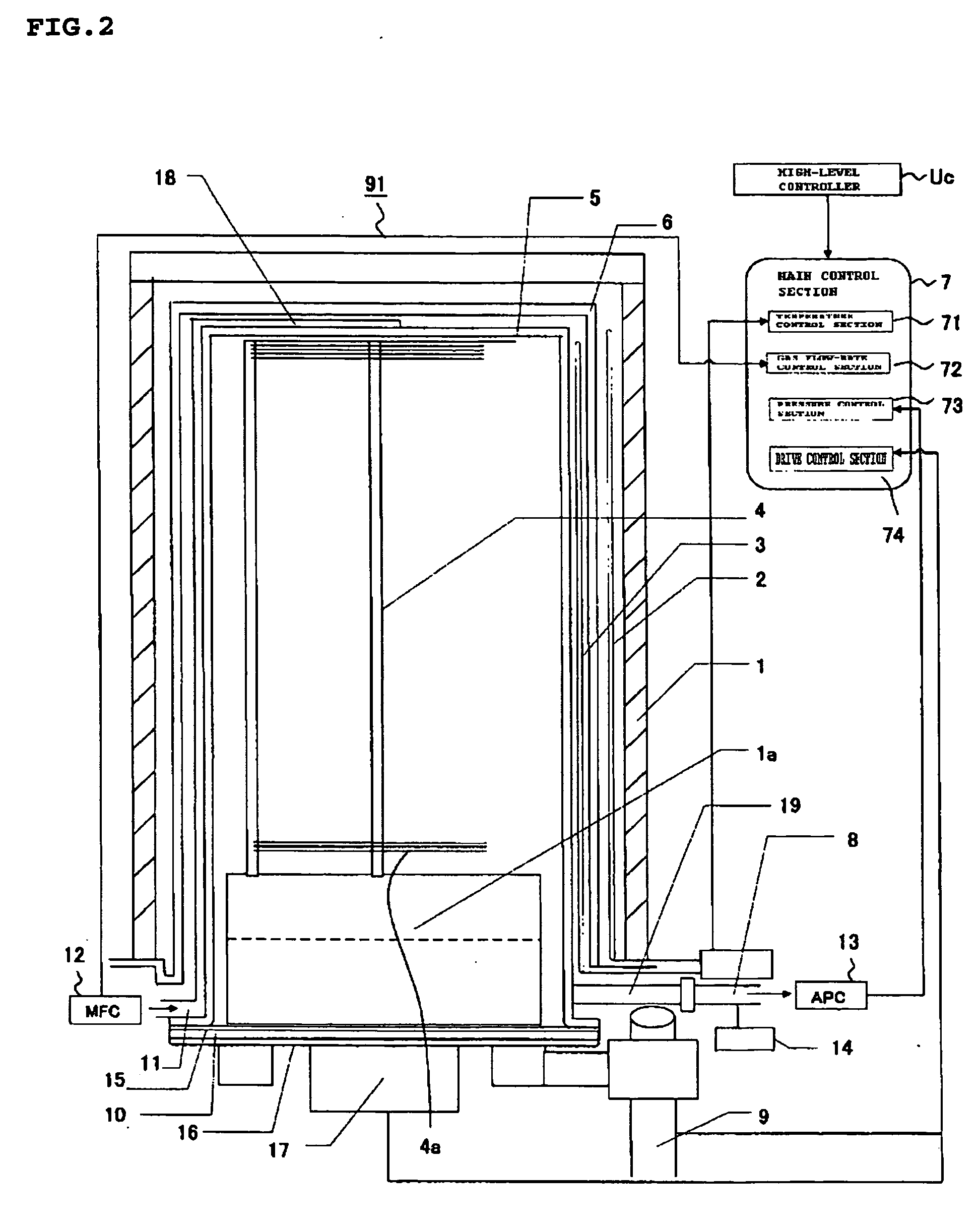
[0033]FIG. 1 is a functional block diagram showing the thermal processing system according to a first embodiment of the present invention. FIG. 2 is a view showing the details of a structure on the periphery of a reactor tube of the same system.
[0034]Thermal Processing System
[0035]The thermal processing system according to this embodiment has a processing oven 91 and a main control section 7. In FIG. 1, only a temperature control section 71 is shown as part of the main control section 7.
[0036]Structure of the Processing Oven
[0037]The processing oven 91 includes a heater (heating unit) 1, a quartz cap 1a, a heater thermocouple 2, a cascade thermocouple 3 (temperature detecting unit) 3, a boat 4, a reaction tube 5, a soaking tube 6, a exhaust tube 8, a boat elevator 9, a base 10, a gas supply tube 11, a mass flow controller (MFC) 12, a pressure regulator (APC) 13, a pressure sensor 14, an O-ring 15, a seal cap 16, a rotary shaft 17, an introduction port 18, and an exhaust port 19.
[003...
second embodiment
[0138]Operations to control and adjust the temperature are simplified by performing these operations using the above-described temperature control and adjustment method shown in the flowchart of FIG. 7. Even when this temperature control and adjustment method is used and operations to control and adjust the temperature have been completed, it is sometimes necessary to subsequently process a substrate under a different set of temperature-setting conditions. Even when the temperature is controlled and adjusted under a different set of temperature-setting conditions, the temperature control and adjustment method shown in the flowchart in FIG. 7 is an effective method that allows the temperature to be controlled and adjusted with high precision and overshoots to be reduced. There are, however, cases in which, of all the temperature-setting conditions, only the processing temperature (target temperature) in the processing chamber at the time of substrate processing is made different from...
example 1
[0141]Described below is a case which a change is made only in the temperature gradient, i.e., the ramp-up rate of a temperature increase, from the desired temperature until the temperature inside the reaction tube reaches the target temperature.
[0142]A case will now be considered in which the above-described temperature control and adjustment method shown in the flowchart of FIG. 7 is used to adjust a set a of temperature-setting conditions selected so that the temperature at the start of a temperature increase is 200° C., the target temperature is 400° C., and the ramp-up rate of the temperature increase from 200° C. to 400° C. is 50° C. / min; and in which an integral output pattern such as the one shown in FIG. 17 is determined.
[0143]A case will also be considered in which the goal is to control the temperature in a subsequent cycle under conditions in which only the ramp-up rate during a temperature increase is different, i.e., under a set b of temperature-setting conditions sele...
PUM
 Abstract
Description
Claims
Application Information
 - R&D
- Intellectual Property
- Life Sciences
- Materials
- Tech Scout
- Unparalleled Data Quality
- Higher Quality Content
- 60% Fewer Hallucinations
Browse by: Latest US Patents, China's latest patents, Technical Efficacy Thesaurus, Application Domain, Technology Topic, Popular Technical Reports.
© 2025 PatSnap. All rights reserved.Legal|Privacy policy|Modern Slavery Act Transparency Statement|Sitemap|About US| Contact US: help@patsnap.com


