Optoelectronic sensor and method for detecting objects with polarized light

a technology of optoelectronic sensors and objects, applied in the field of optoelectronic sensors and methods, can solve the problems of saving significant costs, and achieve the effects of preventing optical overlays or adverse effects, facilitating manual adjustments, and increasing the reach of the sensor

Inactive Publication Date: 2009-04-30
SICK AG
View PDF1 Cites 19 Cited by
  • Summary
  • Abstract
  • Description
  • Claims
  • Application Information

AI Technical Summary

Benefits of technology

[0017]The light source is preferably a source of visible, ultraviolet or infrared light, and it is further preferred that it is a laser diode. Visible light has the advantage that it facilitates manual adjustments. Ultraviolet and infrared light renders the light invisible and thereby provides protection against vandalism because the sensor does not generate a light spot that might attract attention. The absence of a light spot can also be of advantage in certain applications because it does not draw attention to the presence of the sensor.
[0018]It is preferred that the optical axes of the light source and the light receiver are perpendicular to each other. The beam splitter is positioned at the intersection of the two optical axes and arranged at an angle of 45° relative to both optical axes. As will be further explained below, this angle is particularly advantageous with regard to mirror a

Problems solved by technology

This saves significant costs, and since glass is widely used in optical ar

Method used


Image

  • Optoelectronic sensor and method for detecting objects with polarized light
  • Optoelectronic sensor and method for detecting objects with polarized light
  • Optoelectronic sensor and method for detecting objects with polarized light

Examples


second embodiment

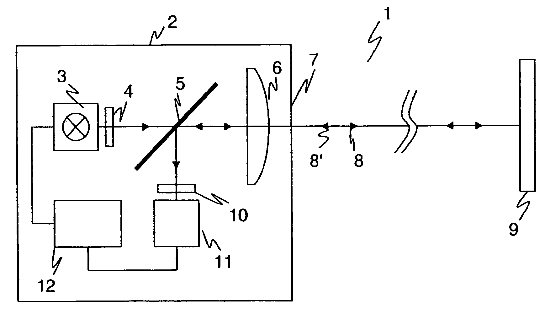
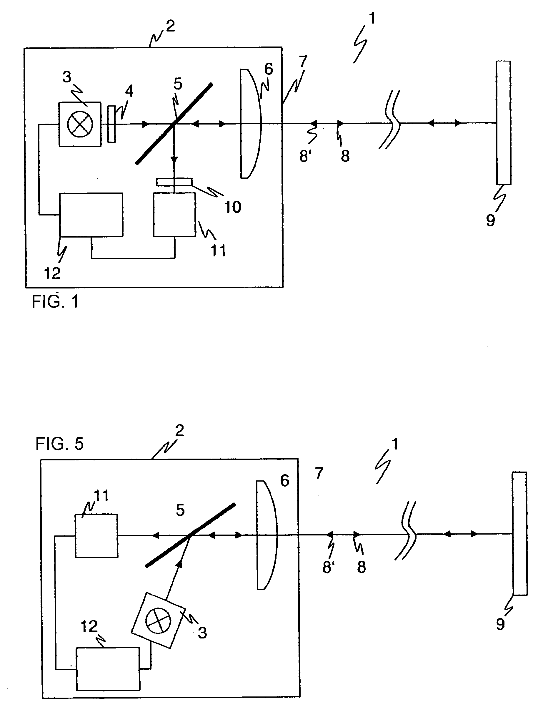
[0056]FIG. 5 shows the present invention. It is similar to the embodiment shown in FIG. 1, and the same reference numerals are used for like elements. The underlying principle of the invention and the advantages derived therefrom remain the same.

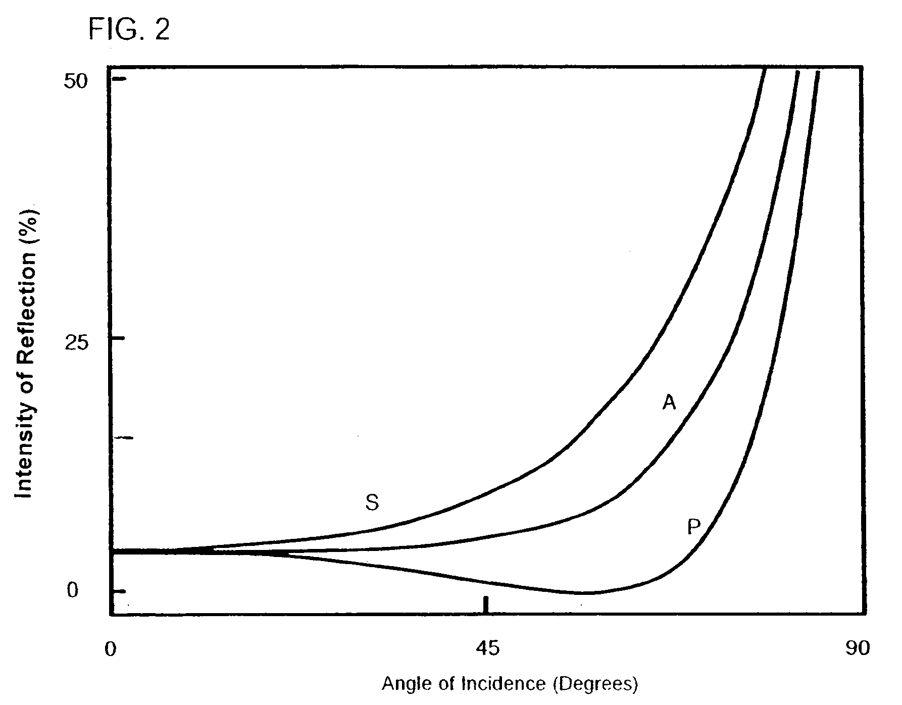
[0057]In contrast to the first embodiment of the invention, the optical axis of light source 3 in this second embodiment of the invention is the Brewster angle relative to beam splitter 5, which, for glass, is 56%. This way the beam splitter simultaneously acts as polarizer 4 because with the Brewster angle only s-polarized light is reflected into light transmission path 8. Following the turning reflection at retroreflector 9, also under the Brewster angle, the now p-polarized reflected light is completely transmitted by beam splitter 5. In this manner, the polarization filter 10 can be eliminated and the beam splitter 5 simultaneously functions as beam splitter, polarizer and polarization filter 10.

first embodiment

[0058]Contrary to the first embodiment, the optical axes of light source 3 and light receiver 11 are not perpendicular to each other. They are arranged so that the light in light transmission path 8 and light reflection path 8′ are at the Brewster angle. The angle, at which the optical axes of light source 3 and light receiver 11 must be positioned, can be calculated with elementary geometry as 180°-2*Brewster angle.

[0059]Thus, the second embodiment of the present invention has the additional advantage that separate polarizers and polarization filters can be eliminated, which provides significant cost savings.


PUM


Abstract

A method and apparatus for detecting objects has a sensor with a light source, a light receiver, and a light retroreflector between them. Light from the source is transmitted to the detector along a light transmission path from the source to the retroreflector and is reflected back to the detector along a light reflection path that substantially corresponds to the transmission path. A single lens or a pair of adjacent lenses shapes the respective light beams from both light emitted by the source and light reflected by the retroreflector in accordance with either the auto collimation principle or the double-eye principle, respectively. A polarizer and a beam splitter are arranged in the light transmission path for light from the source, and a polarization filter is arranged in the light reflection path so that light reflected by the retroreflector passes through the beam splitter and the polarization filter before it reaches the light receiver. A control unit recognizes an interruption of at least one of the light beams as the detection of an object in the light transmission and/or light reflection paths. The beam splitter is a dielectricum which has differing transmission and reflection characteristics for p-polarized light and s-polarized light.

Description

RELATED APPLICATIONS[0001]This application claims priority from German patent application No. 10 2006 053 229.5 filed Nov. 11, 2006, the disclosure of which is incorporated herein by reference.BACKGROUND OF THE INVENTION[0002]This invention relates to optoelectronic sensors as well as a method for detecting objects with light beams emitted by a light source and, following reflection, received by a light receiver.[0003]Optoelectronic sensors are often used for detecting the intrusion of objects into monitored regions. They are used in a variety of ways, from motion detectors via burglary protection to securing automatic doors. The detection of objects is also of importance in the automation industry.[0004]A reflection light barrier is an example of an object detecting sensor which, generally speaking, has a light source, such as an LED, that emits a beam which strikes a retroreflector at the opposite end of the monitored region. The reflector returns the light, and the reflected beam...

Claims


Application Information

Patent Timeline
IPC IPC(8): H01J40/14G01J4/00G08B5/00
CPCG01V8/14
Inventor HOERSCH, INGOLFLANG, FELIXMEIER, ROLF
Owner SICK AG
Why Eureka
Try Eureka