Drain valve actuators and methods of controlling drain valves

a technology of valve actuator and valve valve, which is applied in the direction of motor/generator/converter stopper, dynamo-electric converter control, instruments, etc., can solve the problem that the controller does not provide power to the motor

Active Publication Date: 2009-04-30
MOLON MOTOR & COLL
View PDF8 Cites 12 Cited by
  • Summary
  • Abstract
  • Description
  • Claims
  • Application Information

AI Technical Summary

Benefits of technology

[0007]The present invention provides new valve actuators and related methods. Embodiments of the new valve actuators and related methods can be applied to drain valves of industrial washing machines or other high volume fluid flow drain valves. In an embodiment, the valve actuator has a permanent magnet DC (PMDC) motor which drives a gear train which rotatably drives an output shaft. The output shaft is engaged with the drain valve and moves the drain valve to open and closed positions as desired. The valve actuator also has a controller which controls operation of the valve actuator. The controller provides power to the motor only when needed to open and close the drain valve. The controller does not provide power to the motor when the drain valve is in the open and closed positions. The valve actuator protects the motor from unnecessary electrical power when the valve is not being moved.
[0008]In an embodiment of the present invention, a valve actuator has a housing and an electric motor mounted to the housing in which the motor has a motor shaft. A rotatable output shaft extends through a wall of the housing. A gear train is positioned within the housing and is operatively connected to the motor shaft and to the output shaft. A controller is electrically connected to the motor. The controller has an output signal which drives the motor which drives the gear train which rotates the output shaft from a first position to a second position. The controller also has a signal reducer which reduces the output signal to the motor when the output shaft is in the second position.

Problems solved by technology

The controller does not provide power to the motor when the drain valve is in the open and closed positions.

Method used


Image

  • Drain valve actuators and methods of controlling drain valves
  • Drain valve actuators and methods of controlling drain valves
  • Drain valve actuators and methods of controlling drain valves

Examples


Embodiment Construction

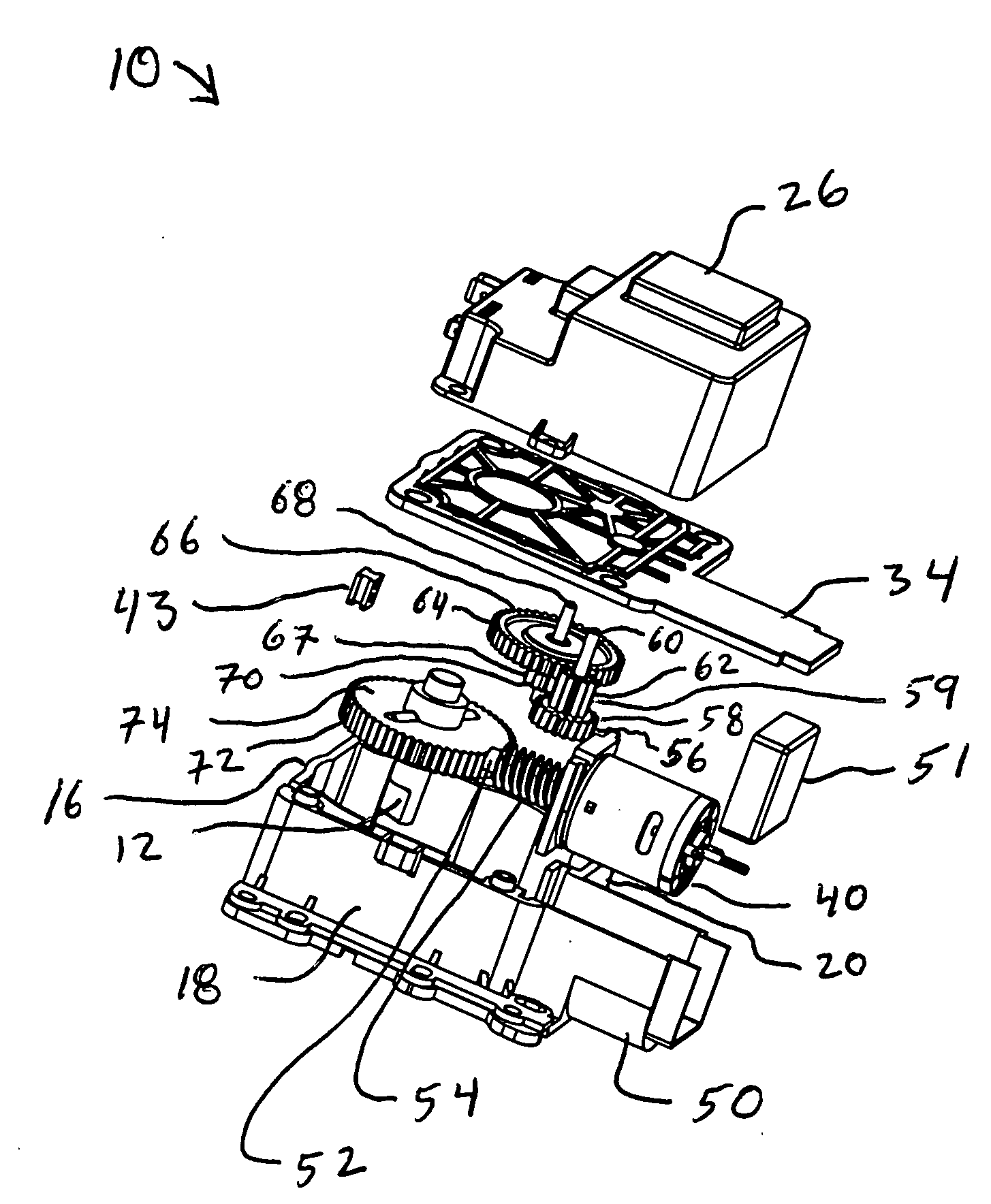
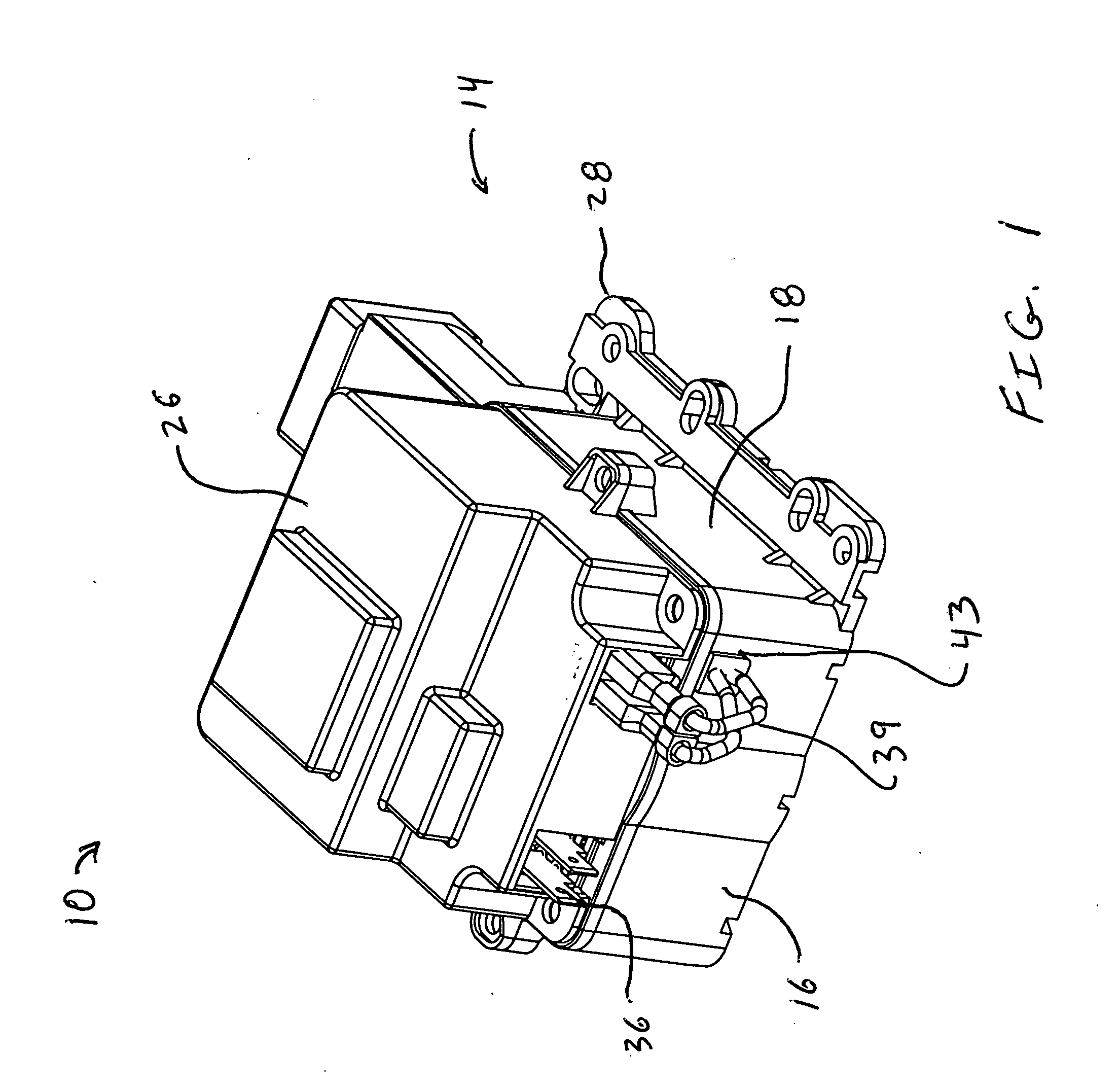
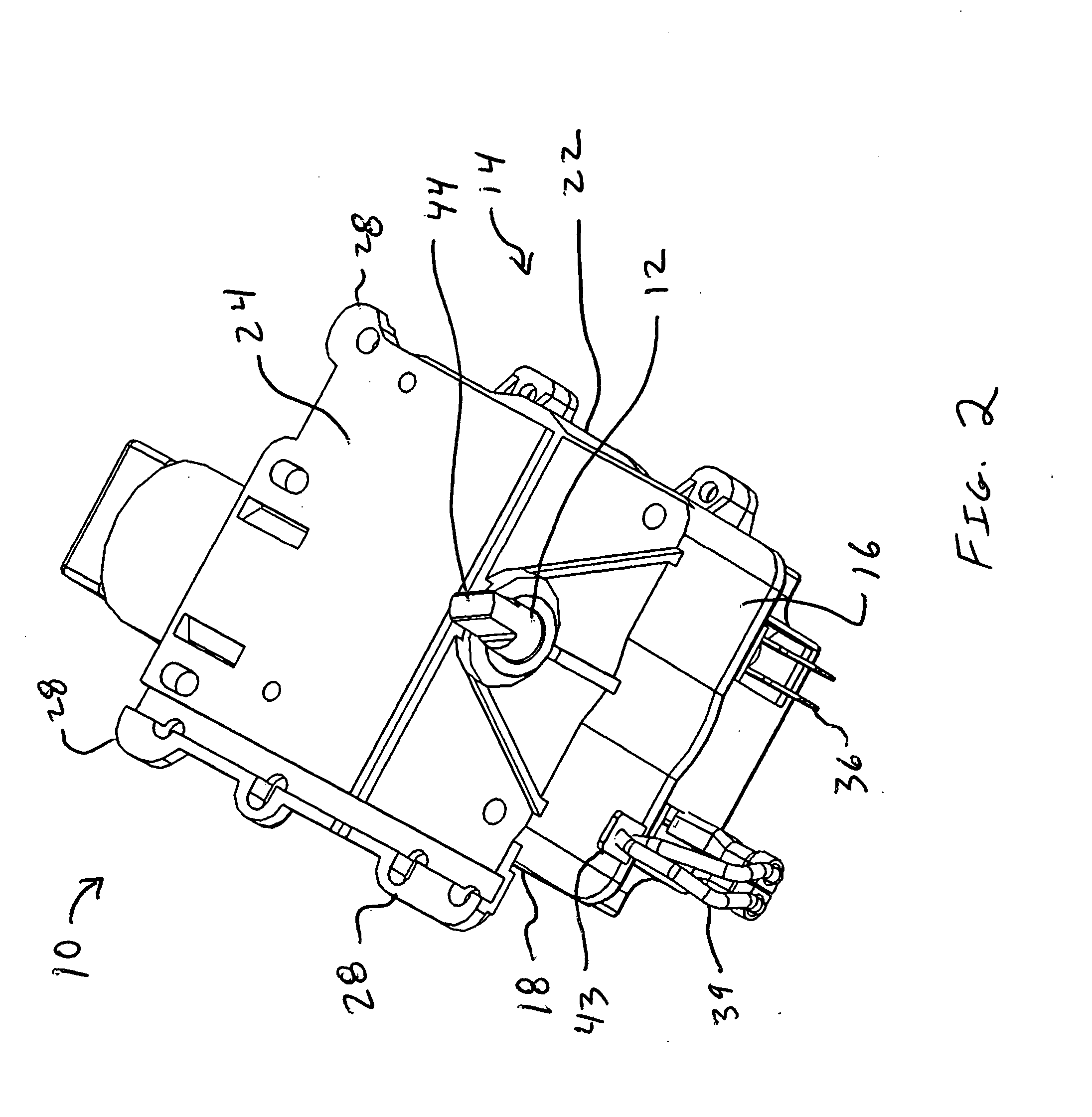
[0034]One example of a drain valve actuator 10 according to the present invention is shown in FIGS. 1-7. FIGS. 1 and 2 show exterior perspective views of opposite sides of the drain valve actuator 10 and FIG. 3 shows a plan view of a side of the drain valve actuator 10 having an output shaft 12. The drain valve actuator 10 has a closed housing 14 with side walls 16, 18, 20, 22, 24 (side wall 20 is shown in FIGS. 5 and 6), and a removable cover 26. The drain valve actuator 10 has mounting brackets 28 on its exterior for mounting the drain valve actuator 10, for example to a drain valve 30 (FIG. 4) of an industrial washing machine (not shown). The output shaft 12 extends through the housing 14, such as through the side wall 24, and can be operatively engaged with the drain valve 30.

[0035]Referring to FIGS. 1 and 7, the drain valve actuator 10 has a controller 32, for example a printed circuit board, which controls operation of the drain valve actuator 10. The controller 32 is housed w...


PUM


Abstract

A valve actuator operates a valve, such as a drain valve of an industrial washing machine. The valve actuator has a permanent magnet DC motor which drives a gear train which rotatably drives an output shaft. The output shaft is engaged with the drain valve and moves the drain valve to open and closed positions as desired. The valve actuator also has a controller which controls operation of the valve actuator. The controller provides power to the motor only when needed to open and close the drain valve. The controller does not provide power to the motor when the drain valve is in the open and closed positions.

Description

BACKGROUND OF THE INVENTION[0001]This invention relates to valve actuators and methods of controlling valves. Embodiments of the present invention pertain to valve actuators for fluid drain valves used in industrial washing machines and other applications with high volume drain flow. Embodiments of the present invention also pertain to methods of controlling high volume drain valves, such as drain valves for industrial washing machines. Although embodiments of the present invention are described as drain valve actuators and related methods, the present invention is not limited to drain valve applications and can be practiced in embodiments applied to valves other than drain valves.[0002]An existing industrial washing machine drain valve actuator has a motor which closes the drain valve against a force of a coil spring which is attached to the output shaft of the motor. The coil spring applies a force to the drain valve in the drain valve open direction. The motor is an AC shaded pol...

Claims


Application Information

Patent Timeline
Patent Type & Authority Applications(United States)
IPC IPC(8): F16K31/02
CPCF16K31/53F16K31/04
Inventor STAEV, STOYAN S.
Owner MOLON MOTOR & COLL
Why Eureka
Try Eureka