Screw type inerter mechanism

Inactive Publication Date: 2009-04-30
NAT TAIWAN UNIV
View PDF9 Cites 68 Cited by
  • Summary
  • Abstract
  • Description
  • Claims
  • Application Information

AI Technical Summary

Benefits of technology

[0018]According to the screw type inerter mechanism of the present invention, if a non-zero external force is applied to the present system so as to generate relative horizontal displacement between the nut and the connection body, the screw rotates and further causes the inertia body to rotate, thereby achieving inerter features. Furthermore, the backlash between the nut and the screw is not so serious as that

Problems solved by technology

Therefore, compared to a conventional mass element, the corresponding electrical element must have one terminal connected to the ground as the reference point, thereby limiting the correspondence between the electrical circuits and the mechanical networks.
However, the conventional mass element limits the correspondence between electrical circuits and mechanical networks.
Therefore, it is a challenge for the academic and the industry to find a two-terminal mechanical elem

Method used


Image

  • Screw type inerter mechanism
  • Screw type inerter mechanism
  • Screw type inerter mechanism

Examples


Example

First Embodiment

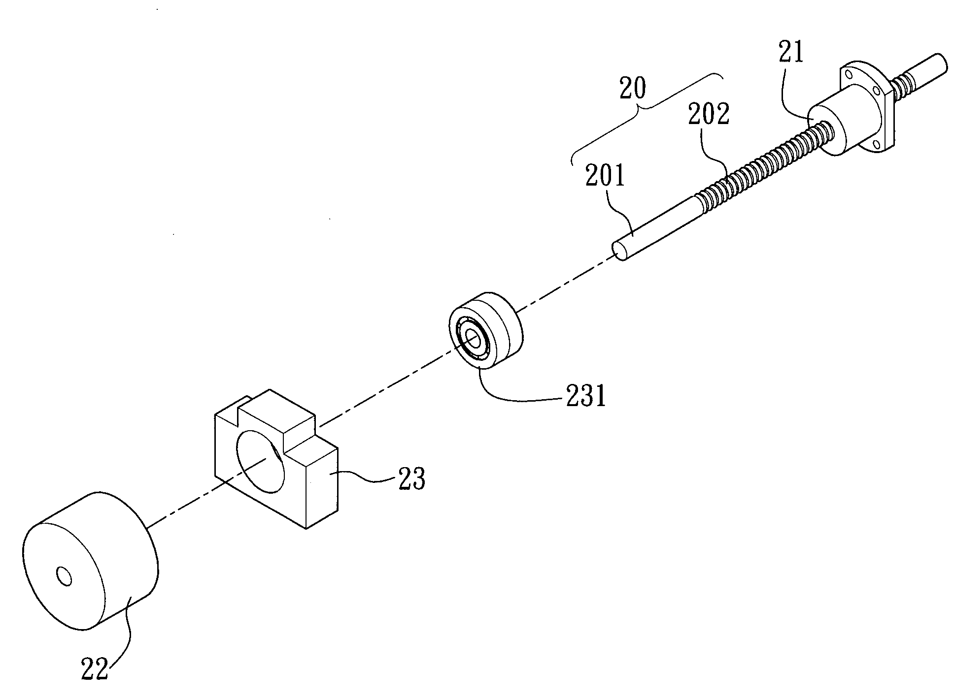
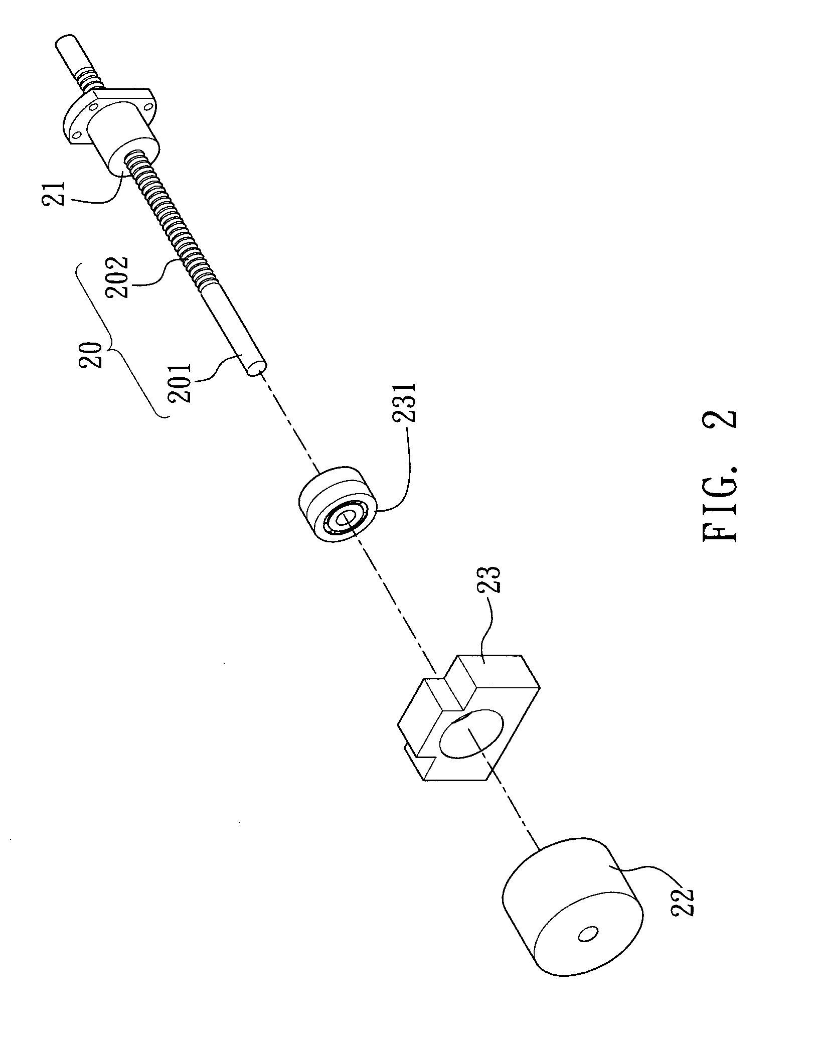
[0028]Referring to FIGS. 2 and 3, a screw type inerter mechanism according to the present invention is disclosed. The screw type inerter mechanism includes a screw 20, which has a limit portion 201 and a thread portion 202 with threads; a nut 21 engaged with the thread portion 202 of the screw 20; an inertia body 22 fixed on the limit portion 201 of the screw 20, wherein the axis of the screw 20 is the rotation axis of the inertia body 22; and a connection body 23 comprising bearings 231, wherein the connection body 23 is engaged with a specific position of the limit portion 201 of the screw 20 through the bearings 231 such that when the screw 20 rotates relatively to the connection body 23, the horizontal and vertical positions of the connection body 23 relative to the screw 20 do not change.

[0029]In the above structure, the engagement portions between the nut 21 and the screw 20 are a ball screw set so as to greatly reduce friction force and eliminate backlash by p...

Example

Second Embodiment

[0033]As shown in FIG. 4, a screw type inerter mechanism is disclosed according to the second embodiment of the present invention. Compared with the first embodiment, the inerter mechanism of the present embodiment further includes an assisting element 211 such as a sleeve connected to the nut 21, wherein the assisting element 211 has a connection point 212 through which an external machine can be connected to the present mechanism. An external force F can be applied to the present mechanism through the assisting element 211 so as to allow the nut 21 to move in parallel with the screw 20, thereby increasing the freedom of connection design and protecting the nut 21 from being damaged by force directly applied thereon.

Example

Third Embodiment

[0034]FIG. 5 is diagram of a screw type inerter mechanism according to the third embodiment of the present invention. In this embodiment, the connection body 23 is connected to an assisting element 50 such as a sleeve, wherein the assisting element 50 encapsulates the inertia body 22, viscous oil 500 is injected into the assisting element 50, and the assisting element 50 is disposed with a connection point 501 for connecting an external machine. Also, an elastic element 60 such as a spring is disposed between the nut 21 and the connection body 23 so as to obtain a mechanical oscillation system including an elastic element, a fluid damper and a screw type inerter mechanism.

[0035]Referring to the motion analysis of the first embodiment, the present embodiment is analyzed using the inerter theory. When an external force F is applied to the oscillation system to generate relative horizontal displacement between the nut 21 and the connection body 23, the screw 20 is brou...


PUM


Abstract

A screw type inerter mechanism includes a screw with a limit portion and a thread portion with threads; a screw cap engaged with the thread portion of the screw; an inertia body fixed to the limit portion of the screw; and a connection body engaged with the limit portion of the screw wherein an axial of the screw serves as a rotation axial for the screw to rotate relatively to the connection body. Thus, when a non-zero external force is applied to the inerter mechanism to generate relative horizontal displacement between the screw cap and the connection body, the screw cap brings the screw to rotate, which further brings the inertia body to rotate, thereby achieving the inerter features.

Description

BACKGROUND OF THE INVENTION[0001]1. Field of the Invention[0002]The present invention relates generally to an inerter mechanism, and more particularly to a screw type inerter mechanism.[0003]2. Description of Related Art[0004]In recent years, mechanical / electrical system integration has become an important trend. In conventional engineering application, there are two ways for a mechanical network to correspond to an electrical circuit. One is ‘force-current’ analogy, wherein mass, damper and spring correspond to capacitor, resistor and inductor, respectively. The other is ‘force-voltage’ analogy, wherein mass, damper and spring correspond to inductor, resistor and capacitor, respectively.[0005]In a mechanical network, springs and dampers are elements with two terminals. However, acceleration of a mass element is measured relative to the ground. In other words, the reference frame of the conventional mass element is limited by Newton's Second Law. Hence, a mass element fails to be a ...

Claims


Application Information

Patent Timeline
IPC IPC(8): F16F15/02F16F7/10F16F9/16F16F15/131
CPCF16F7/1022F16F2232/06F16F9/12
Inventor WANG, FU-CHENGHSU, MAO-SHENGSU, WEI-JIUNLIN, TZ-CHAIN
Owner NAT TAIWAN UNIV
Why Eureka
Try Eureka