Target detection device and its detection method

a detection device and target technology, applied in the field of radar devices, can solve the problems of inability to estimate the location, large change in relative acceleration, and huge time required for operation, and achieve the effect of raising the detection accuracy

Inactive Publication Date: 2009-04-30
NAT TAIWAN UNIV
View PDF22 Cites 5 Cited by
  • Summary
  • Abstract
  • Description
  • Claims
  • Application Information

AI Technical Summary

Benefits of technology

[0013]The main object of this invention is to provide a target detection device and its detection method, which can precisely obtain the component values of the distance, the ve

Problems solved by technology

However, the convergence is unable to be finish in short duration so that this method can only be applied to detect the location of the target, and is unable to be used to estimate the location of target during the next time period.
However, the relative acceleration obtained is subject to big change, and thus is unstable.
However, 256 memory addresses are required for the acquisition of correlation, and 256 samples are needed for the operation of Fourier series and maximum-likelihood estimation so that the time required for the operation is huge.
However, if there is an error, the calculation result will deviate greatly.
But, the r-v formed by using 30 samples is not precise enough.
However, the location of target is unable to be obtained instantaneously.
However, the above system is unable to get relative acceleration.
However, the total operating time will be prolonged by the time required for sampling.
The first method has excessive number of operations

Method used


Image

  • Target detection device and its detection method
  • Target detection device and its detection method
  • Target detection device and its detection method

Examples


Embodiment Construction

[0039]The present invention will become more apparent by the detailed description of specific embodiments in conjunction with the accompanying drawings.

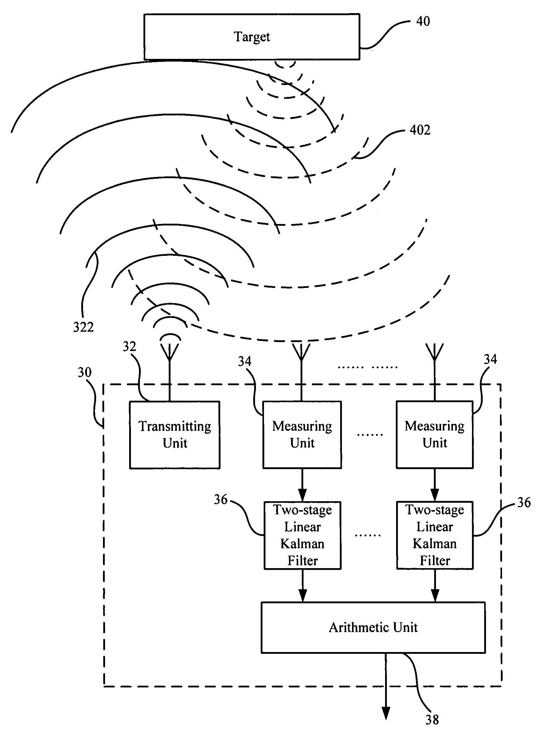
[0040]Referring to FIG. 3, in which a block diagram of an embodiment of the target detection device of the present invention is shown. As shown in FIG. 3, the target detection device 30 comprises a transmitting unit 32, a plurality of measuring units 34, a plurality of two-stage linear Kalman filters 36 and an arithmetic unit 38. Each of the plural two-stage linear Kalman filters 36 supports one of the plural measuring units 34, while the arithmetic unit 38 is connected to the plural two-stage linear Kalman filters 36. When the target detection device 30 is used to detect a target 40, the transmitting unit 32 transmits a detecting pulse 322 for detecting the target 40 which then reflects the detecting pulse 322 to generate a reflected pulse 402. The above detecting pulse 322 is frequency modulation continuous wave (FMCW). Subsequentl...


PUM


Abstract

This invention relates to a target detection device and its detection method, comprising: a transmitting unit for transmitting a detecting pulse to detect target which then reflects the detecting pulse to generate a reflected pulse; a plurality of measuring units, located at different positions respectively which receive said reflected pulse and generates measured values of distance and measured values of velocity according to the reflected pulse received; a plurality of two-stage linear Kalman filters, corresponding to said plural measuring units respectively, each of said plural two-stage linear Kalman filters proceeds an operation according to the measured values produced by corresponding measuring unit so as to generate respectively the estimation values of distance, velocity and acceleration; an arithmetic unit connecting to said plural two-stage linear Kalman filters, which proceeds a triangulation operation according to said estimation values so as to generate distance component values, velocity component values and acceleration component values with respect to the target.

Description

BACKGROUND OF THE INVENTION[0001]1. Field of the Invention[0002]This invention relates to a radar device, particularly to a target detection device and its detection method.[0003]2. Brief Description of the Prior Art[0004]Nowaday, radar device is widely applied for tracking and searching target. In order to enhance the accuracy of radar for tracking target in one respect and to reduce error so as to improve the accuracy of the radar device in another respect, the academic circle and the industries continuously propose the skill to improve the accuracy, such as an article entitled “A new tracker air-to-air missile targets” in the periodical IEEE Trans. Auto. Control, vol. 24, no. 6, December 1979 written by P. S. Maybeck, J. E. Negro, S. J. Cusmanao, and M. D. O. Jr., the radar device firstly obtains the target distance, the azimuth and the elevation angle, then the component values of the target are obtained. However, the convergence is unable to be finish in short duration so that ...

Claims


Application Information

Patent Timeline
IPC IPC(8): G01S13/58
CPCG01S13/003G01S13/723G01S13/582G01S13/46
Inventor KIANG, JEAN-FUTU, PO-JEN
Owner NAT TAIWAN UNIV
Why Eureka
Try Eureka