Liquid Crystal Display Device

a display device and liquid crystal technology, applied in the direction of instruments, final product manufacturing, sustainable manufacturing/processing, etc., can solve the problems of reducing light emission efficiency, affecting the effect of the backlight, and the inability to bend the plate flexibly, etc., to achieve high reliability, increase the effect of area and effectively house the led light sour

Active Publication Date: 2009-04-30
PANASONIC LIQUID CRYSTAL DISPLAY CO LTD
View PDF5 Cites 24 Cited by
  • Summary
  • Abstract
  • Description
  • Claims
  • Application Information

AI Technical Summary

Benefits of technology

[0011]In the liquid crystal display device of the present invention having the backlight which uses LEDs as the light emitting element by taking radiation of heat from the backlight into consideration, the printed circuit board with the increased area can be effectively housed in the ...

Problems solved by technology

In an attempt to realize the high brightness using a large number of LEDs, there arises a drawback that an operating temperature of a liquid crystal display dev...

Method used


Image

  • Liquid Crystal Display Device
  • Liquid Crystal Display Device
  • Liquid Crystal Display Device

Examples


Embodiment Construction

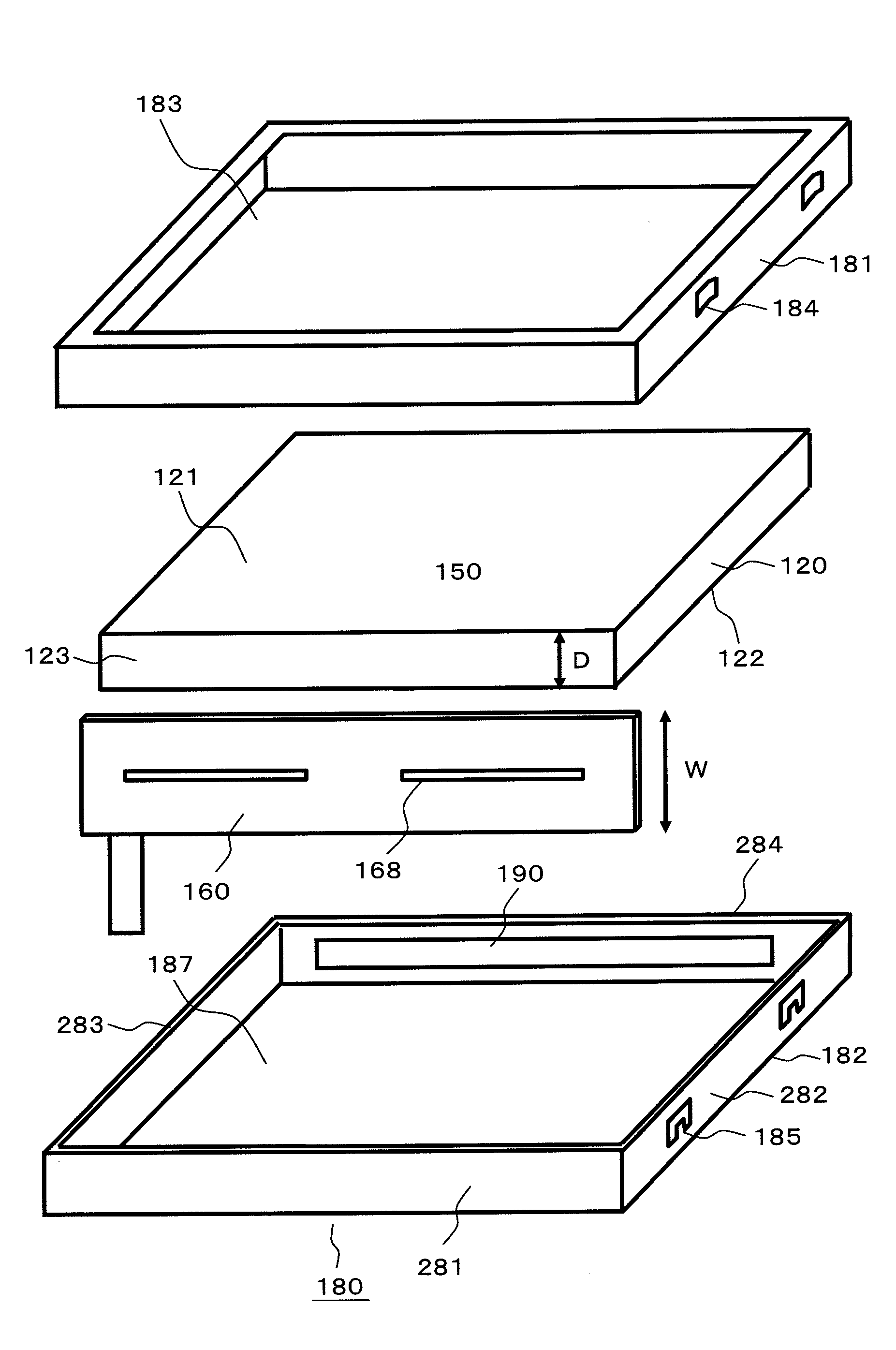
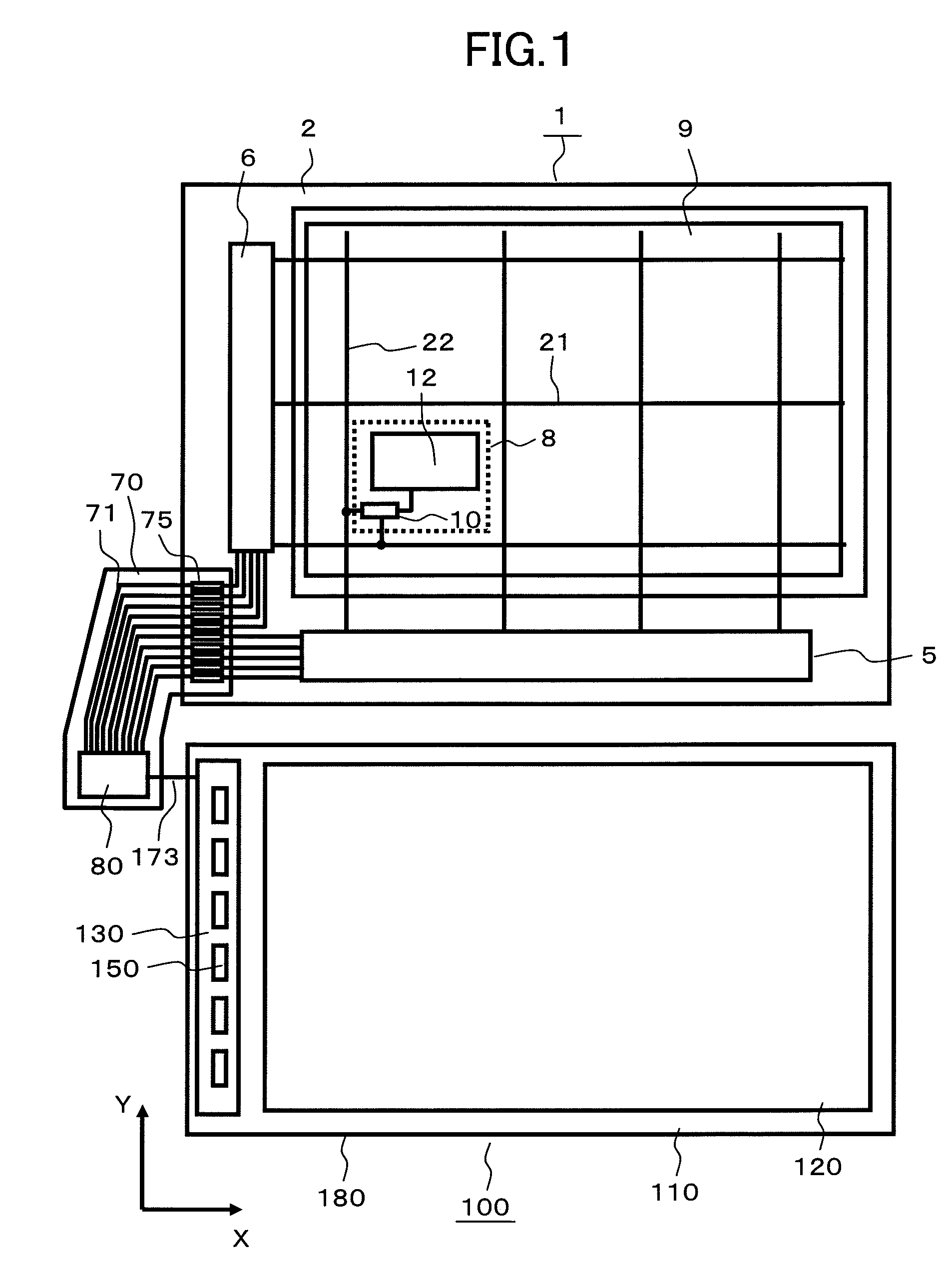
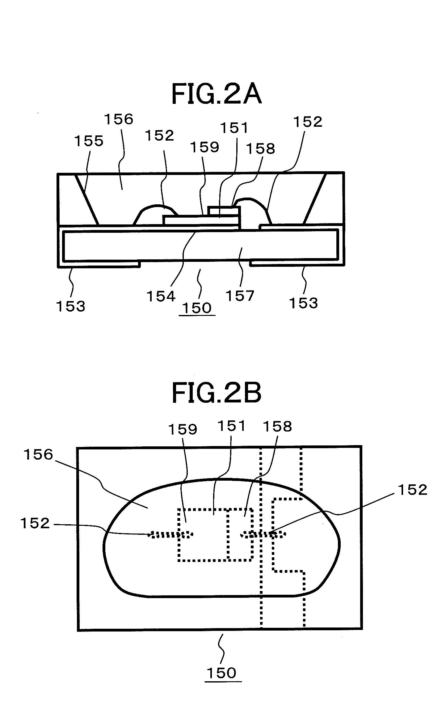
[0025]A liquid crystal display device includes a liquid crystal panel and a backlight which radiates light to the liquid crystal panel. The backlight includes a light guide plate, a plate-shaped light source portion which is formed along one side of the light guide plate, and a housing casing which houses the light guide plate and the plate-shaped light source portion therein. The light guide plate includes a light incident surface on which light emitted from the plate-shaped light source portion is incident, a light radiation surface from which the light is radiated, and a bottom surface which faces the light radiation surface in an opposed manner. A thickness of the light guide plate between the light radiation surface and the bottom surface is set to a fixed value. The plate-shaped light source portion includes the light radiation surface on which the light emitting elements are mounted, and the light radiation surface is arranged to face the light incident surface of the light g...


PUM


Abstract

In a liquid crystal display device which uses light emitting diodes as a light source, the present invention provides a light source which can be effectively housed in a housing casing of a backlight even when an area of a printed circuit board is increased by taking radiation of heat from the light emitting diodes into consideration. A printed circuit board is formed by arranging light emitting diodes on a flexible substrate. The printed circuit board is formed with an area larger than an area of a light incident surface of a light guide plate, and is arranged to face the light incident surface of the light guide plate in an opposed manner. The light guide plate and the printed circuit board are housed in the inside of a housing casing, the printed circuit board is made foldable by forming slits in the printed circuit board thus enabling housing of the printed circuit board in the housing casing in a folded shape. Due to housing of the printed circuit board in a folded shape, a contact area of the printed circuit board with the housing casing is increased thus enhancing a heat radiation effect.

Description

BACKGROUND OF THE INVENTION[0001]1. Field of the Invention[0002]The present invention relates to a light source of a non-self-luminous display device, and more particularly to a liquid crystal display device having a backlight which uses LEDs (light emitting diodes) as a light source.[0003]2. Background Art[0004]Recently, the liquid crystal display device has been popularly used as a display device. Particularly, the liquid crystal display device is used as a display part of portable equipment because the liquid crystal display device is thin and light-weighted and consumes small electric power.[0005]However, the liquid crystal display device is not self-luminous and hence, the liquid crystal display device requires a lighting means. In general, as a lighting device of the liquid crystal display device, a planar lighting device referred to as a backlight is popularly used. Conventionally, although a cold cathode fluorescent tube has been used as a light emitting element (also referr...

Claims


Application Information

Patent Timeline
IPC IPC(8): G02F1/1333
CPCG02B6/0055G02B6/0083G02B6/0085G02F1/133615G02F2001/133628H05K1/0269H01L2224/48227H05K3/303H05K2201/09063H05K2201/09918H05K2201/10106H05K2203/168H05K1/189Y02P70/50G02F1/133628
Inventor WATANABE, SABUROTOKUYAMA, HIROSHIFUKAYAMA, NORIHISA
Owner PANASONIC LIQUID CRYSTAL DISPLAY CO LTD
Why Eureka
Try Eureka