
Programmable integrated microphone interface circuit

a microphone interface and integrated circuit technology, applied in the direction of transducer acoustic reaction prevention, transducer details, electrical transducers, etc., can solve the problems of many limitations, achieve the effect of reducing dc bias noise, saving b.o.m. cost and pcb area in the application, and improving power supply rejection

Active Publication Date: 2009-04-30
WINBOND ELECTRONICS CORP
View PDF14 Cites 21 Cited by
  • Summary
  • Abstract
  • Description
  • Claims
  • Application Information

AI Technical Summary

Benefits of technology

The present invention provides an integrated circuit for a microphone interface that can be used with various types of microphones or other signal sources. The integrated circuit includes an input terminal for receiving an input signal, an output terminal for providing an output signal, and a bias circuit for providing a bias signal. The integrated circuit also includes a first amplifier circuit with differential input and output signals for driving a microphone. The integrated circuit also includes a feedback circuit for providing feedback signals to the amplifier circuit. The technical effects of the invention include improved signal-to-noise ratios, reduced distortion, and improved sensitivity. The invention can be used with a variety of microphones and signal sources, making it highly versatile and adaptable.

Problems solved by technology

Even though conventional interface circuit techniques have been in wide use, they suffer from many limitations, as discussed in more details below.

Method used


Image

  • Programmable integrated microphone interface circuit
  • Programmable integrated microphone interface circuit
  • Programmable integrated microphone interface circuit

Examples


Embodiment Construction

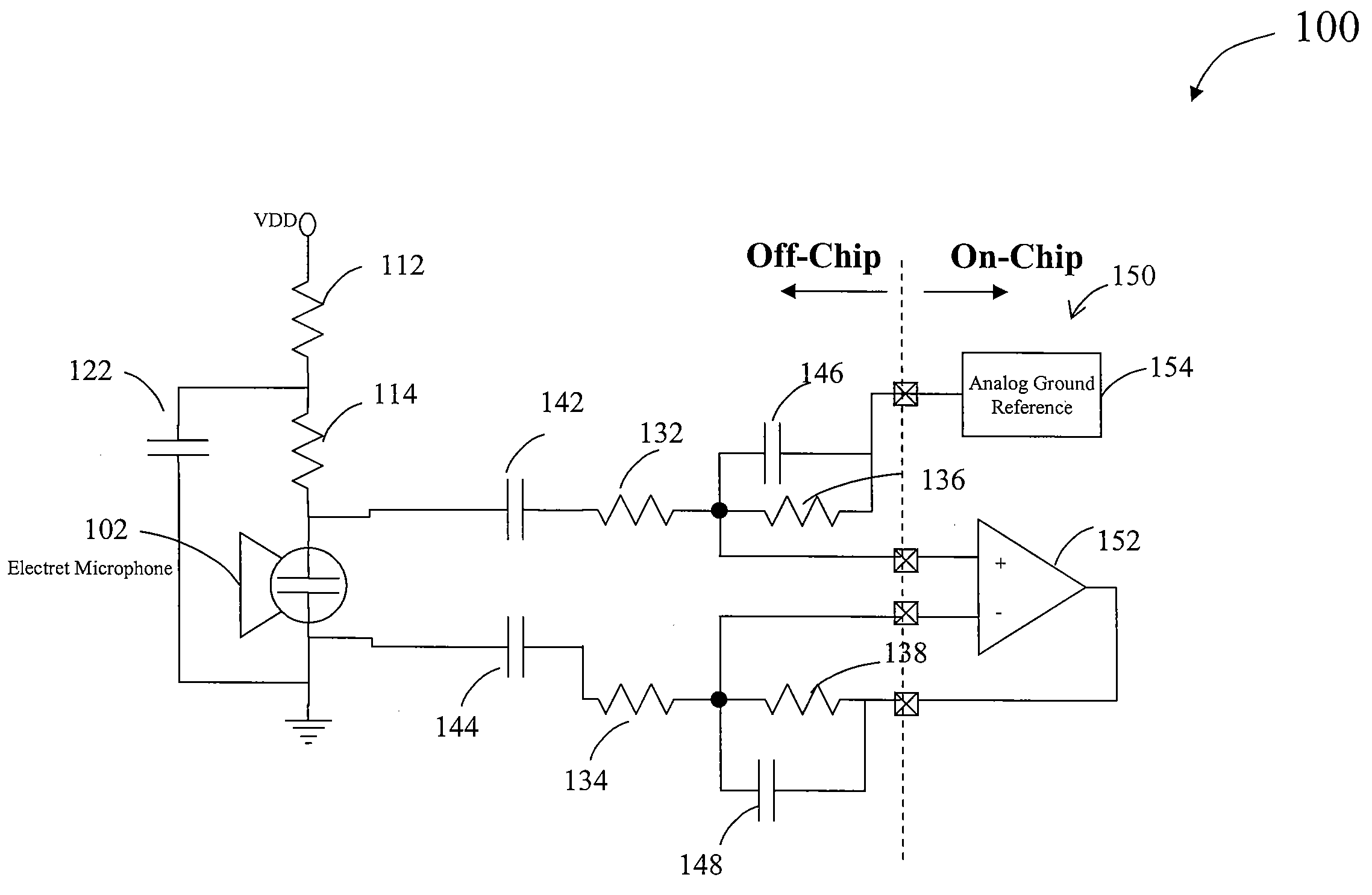
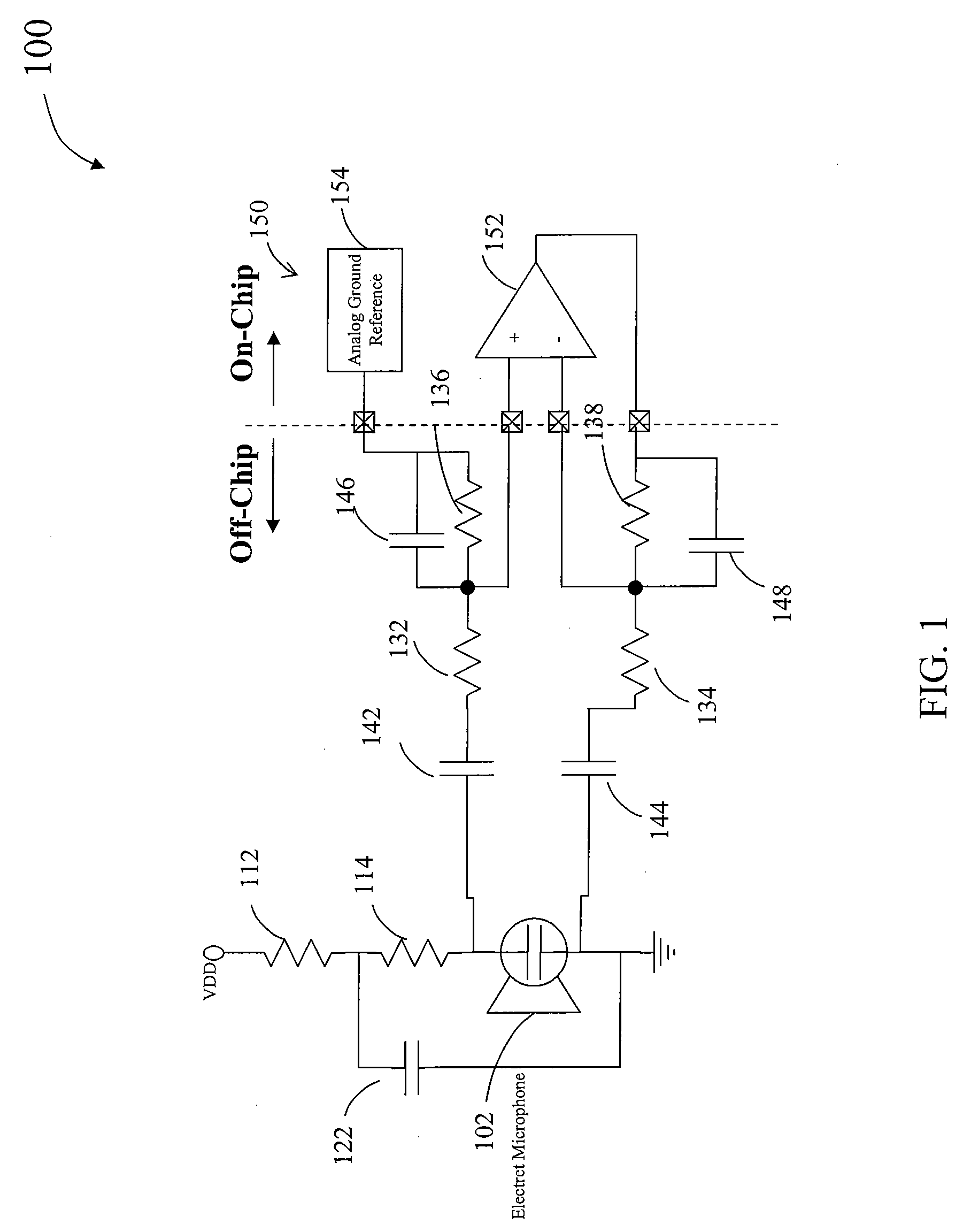
[0042]The present invention is directed to integrated circuits. More particularly, the invention provides a method and device for an integrated circuit for a microphone interface. Merely by way of example, the invention has been applied to interface circuit for an electret microphone. But it would be recognized that the invention has a much broader range of applicability. For example, the invention can be applied to interface circuits to other kinds of microphones or interface circuits to other signal sources.

[0043]According to embodiments of the present invention, conventional techniques for interfacing an electret microphone with a CODEC integrated circuit suffer from many limitations. For example, conventional techniques require many off-chip components. Typically, the bias resistance of the microphone is often small, for example, around 1 kΩ, and the bias filter capacitor often is large, e.g., 68 μF. A purpose of this capacitor is to remove the noise from the bias voltage. The b...


PUM


Abstract

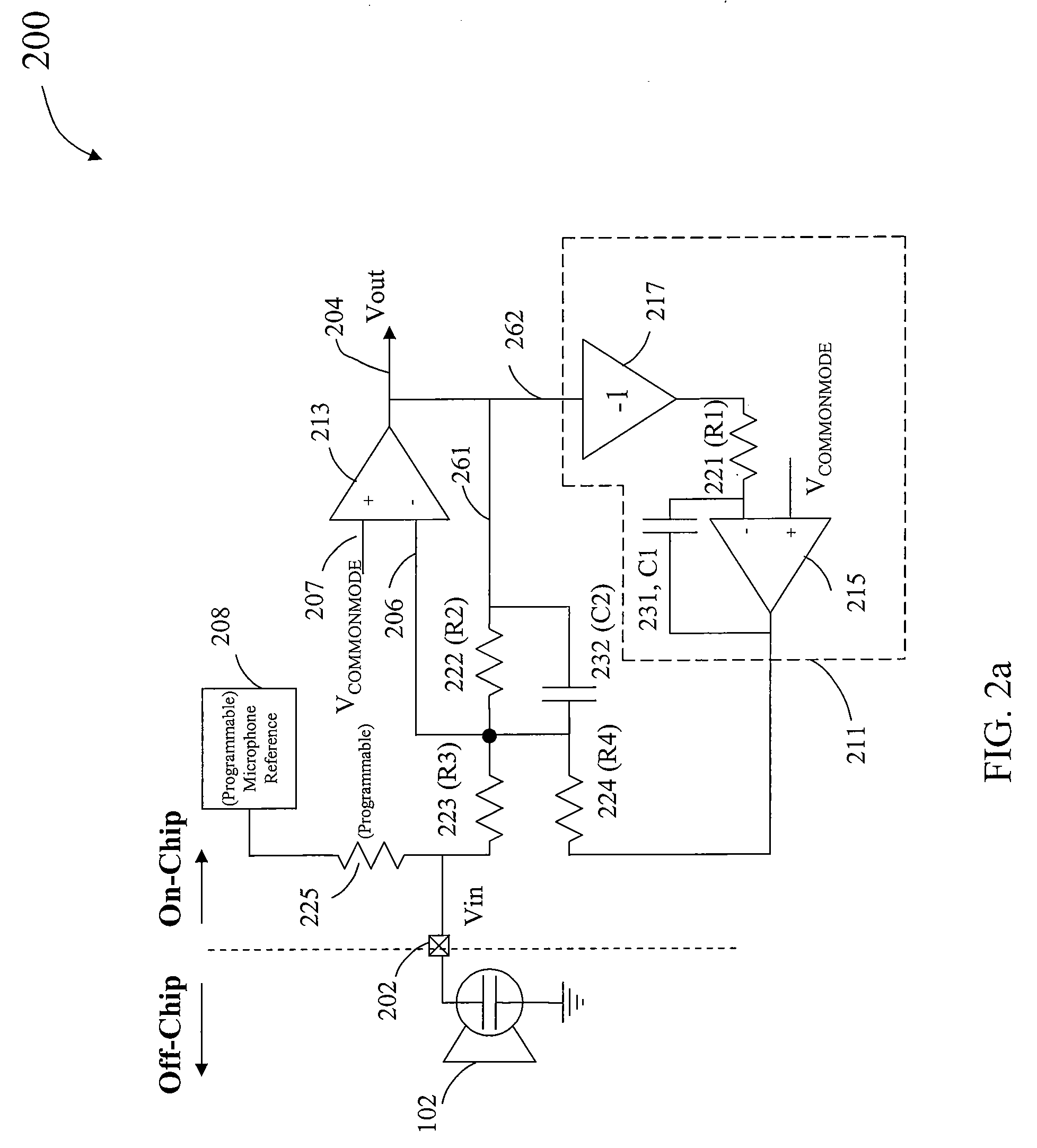
An integrated circuit for providing programmable microphone interface includes an input terminal for receiving an input signal and an output terminal for providing an output audio signal. The integrated circuit includes a bias circuit, an amplifier circuit, and two feedback circuits. The bias circuit provides a microphone bias signal to the microphone and provides a sensed microphone signal. The amplifier circuit includes a first input, a second input, and an output. The first input is configured to receive the sensed microphone signal, a first feedback signal, and a second feedback signal. The second input is configured to receive a first reference signal. The feedback circuits are in communication with the output and the first input of the amplifier circuit. In a specific embodiment, the first feedback circuit includes an RC circuit and the second feedback circuit includes an integrator.

Description

CROSS-REFERENCES TO RELATED APPLICATIONS[0001]This application is related to co-pending U.S. patent application Ser. No. 11 / 761,957, filed Jun. 12, 2007, commonly assigned and incorporated by reference herein for all purposes.BACKGROUND OF THE INVENTION[0002]The present invention is directed to integrated circuits. More particularly, the invention provides a method and device for an integrated circuit for a microphone interface. Merely by way of example, the invention has been applied to interface circuit for an electret microphone. But it would be recognized that the invention has a much broader range of applicability. For example, the invention can be applied to interface circuits to other kinds of microphones or interface circuits to other signal sources.[0003]Voice and audio band applications often use a microphone to pick up the voice or audio energy from the environment and translate it into a voltage or current. Microphones are used in many applications such as telephones, ta...

Claims


Application Information

Patent Timeline
Patent Type & Authority Applications(United States)
IPC IPC(8): H04R3/00
CPCH04R19/016H04R3/02
Inventor HOLZMANN, PETER
Owner WINBOND ELECTRONICS CORP
Learn More